
User`s manual

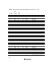

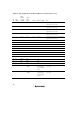


Table Of Contents
- Cover
- Notes regarding these materials
- Contents
- Section 1 System Configuration
- Section 2 Connecting the Emulator to the User System
- 2.1 Connecting the Emulator to the User System
- 2.2 Connecting the Emulator to the User System by Using the EV-chip Unit
- 2.2.1 Connecting the EV-chip Unit to the Emulator
- 2.2.2 Connecting the E200F External Bus Trace Unit to the EV-chip Unit
- 2.2.3 Connecting the Probe Head to the EV-chip Unit
- 2.2.4 Connecting the E200F Emulation Memory Unit to the EV-chip Unit
- 2.2.5 Connecting the E200F External Bus Trace Unit, Emulation Memory Unit, and EV-chip Unit
- 2.2.6 Connecting the EV-chip Unit to the User System Interface Board
- 2.3 Connecting the Emulator to the User System by Using the H-UDI Port Connector
- 2.4 Installing the H-UDI Port Connector on the User System
- 2.5 Pin Assignments of the H-UDI Port Connector
- 2.6 Recommended Circuit between the H-UDI Port Connector and the MCU
- 2.7 Connecting the E200F External Bus Trace Unit with the User System
- 2.8 Installing the External Bus Trace Unit Connector
- 2.8.1 External Bus Trace Unit Connector Installed on the User System
- 2.8.2 Pin Assignments of the User System Connector
- 2.8.3 Recommended Foot Pattern
- 2.8.4 Restrictions on Component Installation
- 2.8.5 Pin Assignments of the External Bus Trace Unit Connector
- 2.8.6 Layout of the External Bus Trace Unit Connector
- 2.9 Connecting the External Bus Trace Unit to the User System
- 2.9.1 Connecting the E200F External Bus Trace Unit to the Emulator Main Unit
- 2.9.2 Connecting the E200F External Bus Trace Unit to the User System
- 2.9.3 Connecting the E200F Emulation Memory Unit to the Emulator Main Unit
- 2.9.4 Connecting the Emulation Memory Unit to the User System
- 2.9.5 Connecting the E200F External Bus Trace Unit, Emulation Memory Unit, and User System
- Section 3 Software Specifications when Using the SH7211
- 3.1 Differences between the SH7211 and the Emulator
- 3.2 Specific Functions for the Emulator when Using the SH7211
- 3.2.1 Event Condition Functions
- 3.2.2 Trace Functions
- 3.2.3 Notes on Using the JTAG (H-UDI) Clock (TCK) and AUD Clock (AUDCK)
- 3.2.4 Notes on Setting the [Breakpoint] Dialog Box
- 3.2.5 Notes on Setting the [Event Condition] Dialog Box and the BREAKCONDITION_ SET Command
- 3.2.6 Performance Measurement Function
- Section 4 User System Interface Circuits
- Colophon

29
Table 2.4 Pin Assignments of the External Bus Trace Unit Connector (cont)
Pin
No.
I/O
(CONT)
E200F
Trace I/F
Connector
Pin Name
SH7211
Signal
Name
Voltage
Meaning of Signal
Note
123 I UCONT-P2 _WE2/
_DQMLU
3.3 V Upper-byte write
signals/upper-byte
signals of SDRAM
(D23-D16)
Connect the _WE2 signal of the MPU (fix _WE2
to high level when it is not used).
124 I UCONT-P3 _WE3 3.3 V Most-upper-byte write
signals (D31-D24)
Connect the _WE3 signal of the MPU (fix _WE3
to high level when it is not used).
125 I UCONT-P4 _RD 3.3 V Read signal Connect the _RD signal of the MPU
(necessary).
126 I UCONT-P5 _BS 3.3 V Bus cycle start signal Connect the _BS signal of the MPU (fix _BS to
high level when it is not used).
127 I UCONT-P6 N.C -
128 I UCONT-P7 N.C -
129 I UCONT-P8 N.C -
130 I UCONT-P9 MD0 3.3 V Operating mode
setting
Connect the MD_0 signal of the MPU
(necessary).
131 I UCONT-P10 MD1 3.3 V Operating mode
setting
Connect the MD_1 signal of the MPU
(necessary).
132 I UCONT-P11 N.C -
133 I UCONT-P12 N.C -
134 I UCONT-P13 N.C -
135 I UCONT-P14 N.C -
136 I UCONT-P15 N.C -
137 I UCONT-P16 _DACK0 3.3 V User pin signal Connect the _DACK0 signal of the MPU (fix
_DACK0 to high level when it is not used).
138 I UCONT-P17 _DACK1 3.3 V User pin signal Connect the _DACK1 signal of the MPU (fix
_DACK1 to high level when it is not used).
139 I UCONT-P18 _DACK2 3.3 V User pin signal Connect the _DACK2 signal of the MPU (fix
_DACK2 to high level when it is not used).
140 I UCONT-P19 _DACK3 3.3 V User pin signal Connect the _DACK3 signal of the MPU (fix
_DACK3 to high level when it is not used).
141 I UCONT-P20 _RES 3.3 V Power-on reset
request
Connect the _RES signal of the MPU
(necessary).