
User`s manual


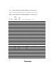
Table Of Contents
- Cover
- Notes regarding these materials
- Contents
- Section 1 System Configuration
- Section 2 Connecting the Emulator to the User System
- 2.1 Connecting the Emulator to the User System
- 2.2 Connecting the Emulator to the User System by Using the EV-chip Unit
- 2.2.1 Connecting the EV-chip Unit to the Emulator
- 2.2.2 Connecting the E200F External Bus Trace Unit to the EV-chip Unit
- 2.2.3 Connecting the Probe Head to the EV-chip Unit
- 2.2.4 Connecting the E200F Emulation Memory Unit to the EV-chip Unit
- 2.2.5 Connecting the E200F External Bus Trace Unit, Emulation Memory Unit, and EV-chip Unit
- 2.2.6 Connecting the EV-chip Unit to the User System Interface Board
- 2.3 Connecting the Emulator to the User System by Using the H-UDI Port Connector
- 2.4 Installing the H-UDI Port Connector on the User System
- 2.5 Pin Assignments of the H-UDI Port Connector
- 2.6 Recommended Circuit between the H-UDI Port Connector and the MCU
- 2.7 Connecting the E200F External Bus Trace Unit with the User System
- 2.8 Installing the External Bus Trace Unit Connector
- 2.8.1 External Bus Trace Unit Connector Installed on the User System
- 2.8.2 Pin Assignments of the User System Connector
- 2.8.3 Recommended Foot Pattern
- 2.8.4 Restrictions on Component Installation
- 2.8.5 Pin Assignments of the External Bus Trace Unit Connector
- 2.8.6 Layout of the External Bus Trace Unit Connector
- 2.9 Connecting the External Bus Trace Unit to the User System
- 2.9.1 Connecting the E200F External Bus Trace Unit to the Emulator Main Unit
- 2.9.2 Connecting the E200F External Bus Trace Unit to the User System
- 2.9.3 Connecting the E200F Emulation Memory Unit to the Emulator Main Unit
- 2.9.4 Connecting the Emulation Memory Unit to the User System
- 2.9.5 Connecting the E200F External Bus Trace Unit, Emulation Memory Unit, and User System
- Section 3 Software Specifications when Using the SH7211
- 3.1 Differences between the SH7211 and the Emulator
- 3.2 Specific Functions for the Emulator when Using the SH7211
- 3.2.1 Event Condition Functions
- 3.2.2 Trace Functions
- 3.2.3 Notes on Using the JTAG (H-UDI) Clock (TCK) and AUD Clock (AUDCK)
- 3.2.4 Notes on Setting the [Breakpoint] Dialog Box
- 3.2.5 Notes on Setting the [Event Condition] Dialog Box and the BREAKCONDITION_ SET Command
- 3.2.6 Performance Measurement Function
- Section 4 User System Interface Circuits
- Colophon

24
2.8.5 Pin Assignments of the External Bus Trace Unit Connector
Table 2.4 shows the pin assignments of the external bus trace unit connector.
Table 2.4 Pin Assignments of the External Bus Trace Unit Connector
Pin
No.
I/O
(CONT)
E200F
Trace I/F
Connector
Pin Name
SH7211
Signal
Name
Voltage
Meaning of Signal
Note
1 I UA-P0 A0 3.3 V Address bus Connect the address signal of the MPU.
2 I UA-P1 A1 3.3 V Address bus Same as above.
3 I UA-P2 A2 3.3 V Address bus Same as above.
4 I UA-P3 A3 3.3 V Address bus Same as above.
5 I UA-P4 A4 3.3 V Address bus Same as above.
6 I UA-P5 A5 3.3 V Address bus Same as above.
7 I UA-P6 A6 3.3 V Address bus Same as above.
8 I UA-P7 A7 3.3 V Address bus Same as above.
9 - GND GND GND
10 - GND GND GND
11 I UA-P8 A8 3.3 V Address bus Connect the address signal of the MPU.
12 I UA-P9 A9 3.3 V Address bus Same as above.
13 I UA-P10 A10 3.3 V Address bus Same as above.
14 I UA-P11 A11 3.3 V Address bus Same as above.
15 I UA-P12 A12 3.3 V Address bus Same as above.
16 I UA-P13 A13 3.3 V Address bus Same as above.
17 I UA-P14 A14 3.3 V Address bus Same as above.
18 I UA-P15 A15 3.3 V Address bus Same as above.
19 - GND GND GND
20 - GND GND GND
21 I UA-P16 A16 3.3 V Address bus Connect the address signal of the MPU.
22 I UA-P17 A17 3.3 V Address bus Same as above.
23 I UA-P18 A18 3.3 V Address bus Same as above.
24 I UA-P19 A19 3.3 V Address bus Same as above.
25 I UA-P20 A20 3.3 V Address bus Same as above.