
User`s manual


Table Of Contents
- Cover
- Notes regarding these materials
- Contents
- Section 1 System Configuration
- Section 2 Connecting the Emulator to the User System
- 2.1 Connecting the Emulator to the User System
- 2.2 Connecting the Emulator to the User System by Using the EV-chip Unit
- 2.2.1 Connecting the EV-chip Unit to the Emulator
- 2.2.2 Connecting the E200F External Bus Trace Unit to the EV-chip Unit
- 2.2.3 Connecting the Probe Head to the EV-chip Unit
- 2.2.4 Connecting the E200F Emulation Memory Unit to the EV-chip Unit
- 2.2.5 Connecting the E200F External Bus Trace Unit, Emulation Memory Unit, and EV-chip Unit
- 2.2.6 Connecting the EV-chip Unit to the User System Interface Board
- 2.3 Connecting the Emulator to the User System by Using the H-UDI Port Connector
- 2.4 Installing the H-UDI Port Connector on the User System
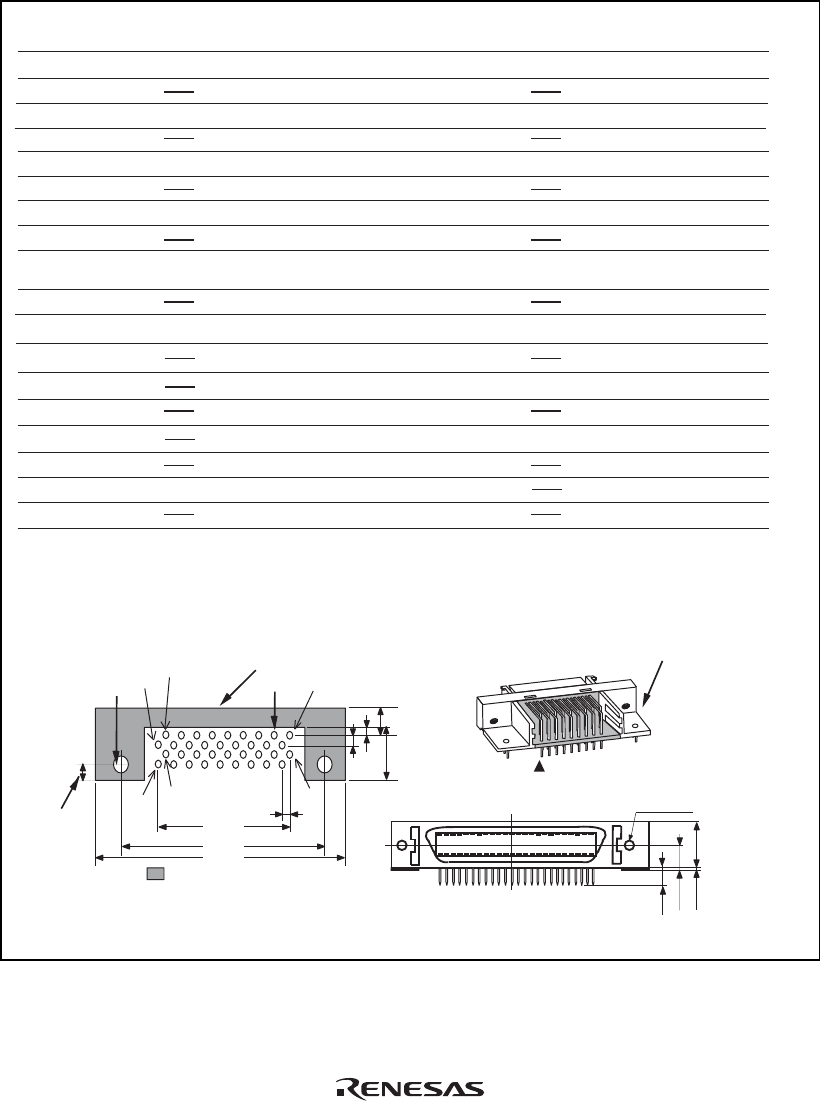
- 2.5 Pin Assignments of the H-UDI Port Connector
- 2.6 Recommended Circuit between the H-UDI Port Connector and the MCU
- 2.7 Connecting the E200F External Bus Trace Unit with the User System
- 2.8 Installing the External Bus Trace Unit Connector
- 2.8.1 External Bus Trace Unit Connector Installed on the User System
- 2.8.2 Pin Assignments of the User System Connector
- 2.8.3 Recommended Foot Pattern
- 2.8.4 Restrictions on Component Installation
- 2.8.5 Pin Assignments of the External Bus Trace Unit Connector
- 2.8.6 Layout of the External Bus Trace Unit Connector
- 2.9 Connecting the External Bus Trace Unit to the User System
- 2.9.1 Connecting the E200F External Bus Trace Unit to the Emulator Main Unit
- 2.9.2 Connecting the E200F External Bus Trace Unit to the User System
- 2.9.3 Connecting the E200F Emulation Memory Unit to the Emulator Main Unit
- 2.9.4 Connecting the Emulation Memory Unit to the User System
- 2.9.5 Connecting the E200F External Bus Trace Unit, Emulation Memory Unit, and User System
- Section 3 Software Specifications when Using the SH7211
- 3.1 Differences between the SH7211 and the Emulator
- 3.2 Specific Functions for the Emulator when Using the SH7211
- 3.2.1 Event Condition Functions
- 3.2.2 Trace Functions
- 3.2.3 Notes on Using the JTAG (H-UDI) Clock (TCK) and AUD Clock (AUDCK)
- 3.2.4 Notes on Setting the [Breakpoint] Dialog Box
- 3.2.5 Notes on Setting the [Event Condition] Dialog Box and the BREAKCONDITION_ SET Command
- 3.2.6 Performance Measurement Function
- Section 4 User System Interface Circuits
- Colophon
19
AUDCK
N.C.
TCK
GND
AU DATA0
GND
AU DATA1
GND
GND
GND
GND
GND
GND
GND
AU DATA2
AU DATA3
UVCC
TMS
GND
N.C.
GND
(GND)
TDI
GND
GND
GND
GND
GND
GND
GND
TDO
1
2
3
4
5
6
7
8
9
10
11
12
13
14
15
16
17
18
19
20
21
22
23
24
25
26
27
28
29
30
31
32
33
34
35
36
_AUDSYNC
_RES
_TRST
_ASEBRKAK
/_ASEBRK
N.C.
Pin
No.
Signal
Input/
Output
Note
Pin
No.
Signal
Input/
Output
Note
*1
*1
User reset
*2
*2
*3
*4
*2
*2
Input
Input
Input
Input
Output
Output
Output
Output
Output
Output Output
Output
Output
Output
Input/
output
1. Input to or output from the user system.
2. The symbol (_) means that the signal is active-low.
Notes:
H-UDI port connector
(Pin 1 mark)
(top view)
Unit: mm
4.8
M2.6 x 0.45
9.0
0.3
3.9
H-UDI port connector (front view)
3. The emulator monitors the GND signal of the user system and detects whether or not the user system is connected.
4. When the E200F probe head is connected to this pin and the _ASEMD pin is set to 0, do not connect to GND
but to the _ASEMD pin directly.
: Pattern inhibited area
Edge of the board
(connected to the connector)
0.7
+0.1
0
2
1.27
1
3
4.5
1.1
1.905
9.0
21.59
37.61
43.51
36
35
4
2.8
+0.1
0
φ
4.09
H-UDI port connector (top view)
φ
Figure 2.10 Pin Assignments of the H-UDI Port Connector (36 Pins)