
User`s manual


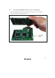

Table Of Contents
- Cover
- Notes regarding these materials
- Contents
- Section 1 System Configuration
- Section 2 Connecting the Emulator to the User System
- 2.1 Connecting the Emulator to the User System
- 2.2 Connecting the Emulator to the User System by Using the EV-chip Unit
- 2.2.1 Connecting the EV-chip Unit to the Emulator
- 2.2.2 Connecting the E200F External Bus Trace Unit to the EV-chip Unit
- 2.2.3 Connecting the Probe Head to the EV-chip Unit
- 2.2.4 Connecting the E200F Emulation Memory Unit to the EV-chip Unit
- 2.2.5 Connecting the E200F External Bus Trace Unit, Emulation Memory Unit, and EV-chip Unit
- 2.2.6 Connecting the EV-chip Unit to the User System Interface Board
- 2.3 Connecting the Emulator to the User System by Using the H-UDI Port Connector
- 2.4 Installing the H-UDI Port Connector on the User System
- 2.5 Pin Assignments of the H-UDI Port Connector
- 2.6 Recommended Circuit between the H-UDI Port Connector and the MCU
- 2.7 Connecting the E200F External Bus Trace Unit with the User System
- 2.8 Installing the External Bus Trace Unit Connector
- 2.8.1 External Bus Trace Unit Connector Installed on the User System
- 2.8.2 Pin Assignments of the User System Connector
- 2.8.3 Recommended Foot Pattern
- 2.8.4 Restrictions on Component Installation
- 2.8.5 Pin Assignments of the External Bus Trace Unit Connector
- 2.8.6 Layout of the External Bus Trace Unit Connector
- 2.9 Connecting the External Bus Trace Unit to the User System
- 2.9.1 Connecting the E200F External Bus Trace Unit to the Emulator Main Unit
- 2.9.2 Connecting the E200F External Bus Trace Unit to the User System
- 2.9.3 Connecting the E200F Emulation Memory Unit to the Emulator Main Unit
- 2.9.4 Connecting the Emulation Memory Unit to the User System
- 2.9.5 Connecting the E200F External Bus Trace Unit, Emulation Memory Unit, and User System
- Section 3 Software Specifications when Using the SH7211
- 3.1 Differences between the SH7211 and the Emulator
- 3.2 Specific Functions for the Emulator when Using the SH7211
- 3.2.1 Event Condition Functions
- 3.2.2 Trace Functions
- 3.2.3 Notes on Using the JTAG (H-UDI) Clock (TCK) and AUD Clock (AUDCK)
- 3.2.4 Notes on Setting the [Breakpoint] Dialog Box
- 3.2.5 Notes on Setting the [Event Condition] Dialog Box and the BREAKCONDITION_ SET Command
- 3.2.6 Performance Measurement Function
- Section 4 User System Interface Circuits
- Colophon
6
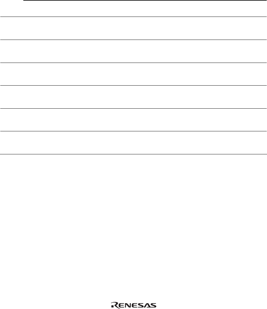
Table 1.3 System Configuration Supported by the SH7211 E200F (cont)
E200F Emulator
EV-chip Unit
External Bus
Trace Unit
Emulation Memory
Unit
Expansion
Profiling Unit
Trace Cable
User System
Interface Board
R0E0200F1EMU00
R0E572110VKK00
R0E0200F1ETU00
R0E0200F1MSR00
R0E0200F1MSR01
R0E0200F0EPU00
R0E0200F0ACC00
R0E572110CFK00
System
configu-
ration 11
*1
Supported Not supported Supported Supported Supported Supported Not supported
System
configu-
ration 12
*1
Supported Not supported Not supported Supported Supported Supported Not supported
System
configu-
ration 13
Supported Supported Not supported Not supported Supported Supported Supported
*2
System
configu-
ration 14
Supported Supported Not supported Supported Supported Supported Supported
*2
System
configu-
ration 15
Supported Supported Supported Not supported Supported Supported Supported
*2
System
configu-
ration 16
Supported Supported Supported Supported Supported Supported Supported
*2
Notes: 1. When the EV-chip unit is not used, the H-UDI port connector must be installed on the user
system. When designing the user system, refer to section 2.3, Connecting the Emulator to
the User System by Using the H-UDI Port Connector. For this system configuration, note
that the H-UDI and AUD pins of the MCU are occupied by the emulator.
2. The user system interface board is only used when the emulator is connected to the user
system; it is not required when the emulator system operates alone.