
Datasheet

RJH1CV6DPK Preliminary
R07DS0747EJ0300 Rev.3.00 Page 4 of 9
Feb 14, 2013
60
80
40
20
0
1.0
4.0
3.5
2.5
3.0
2.0
1.5
10
8
6
4
2
0
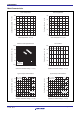
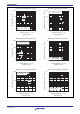
Typical Transfer Characteristics
Collector Current I
C
(A)
Gate to Emitter Voltage V
GE
(V)
Gate to Emitter Cutoff Voltage
vs. Case Temparature (Typical)
−25 0257512550 100 150
Gate to Emitter Cutoff Voltage V
GE(off)
(V)
V
CE
= 10 V
Pulse Test
Case Temparature Tc (
°
C)
1 mA
I
C
= 10 mA
Gate to Emitter Voltage V
GE
(V)
1
3
2
4
5
1
3
2
4
5
8 12 201610 1814812 201610 18
14
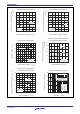
Collector to Emitter Satularion Voltage
vs.
Gate to Emitter Voltage (Typical)
Collector to Emitter Satularion Voltage
vs.
Gate to Emitter Voltage (Typical)
Collector to Emitter Satularion Voltage
V
CE(sat)
(V)
Collector to Emitter Satularion Voltage
V
CE(sat)
(V)
Gate to Emitter Voltage V
GE
(V)
Tc = 25
°
C
Pulse Test
Tc = 150
°
C
Pulse Test
I
C
= 60 A
30 A
I
C
= 60 A
30 A
0 4812 2016
Tc= 25
°
C
150
°
C
V
CE
= 10 V
Pulse Test
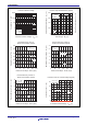
Collector to Emitter Saturation Voltage
vs. Case Temparature (Typical)
−25 0257512550 100 150
Collector to Emitter Saturation Voltage
V
CE(sat)
(V)
Case Temparature Tc (
°
C)
30 A
I
C
= 60 A
V
GE
= 15 V
Pulse Test
25
20
15
10
5
0
Frequency Characteristics (Typical)
Collector Current I
C(RMS)
(A)
Frequency f (kHz)
110010 1000
Tj = 125°C
Tc = 90°C
V
CE
= 400 V
V
GE
= 15 V
Rg = 5 Ω
duty = 50%
0
Collector current wave
(Square wave)