
Datasheet


RJH1CV5DPK Preliminary
R07DS0746EJ0300 Rev.3.00 Page 4 of 9
Feb 14, 2013
20
16
12
8
4
1
5
4
3
2
10
8
6
4
2
0
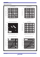
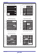
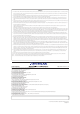
Typical Transfer Characteristics
Collector Current I
C
(A)
Gate to Emitter Voltage V
GE
(V)
Gate to Emitter Cutoff Voltage
vs. Case Temparature (Typical)
−25 0257512550 100 150
Gate to Emitter Cutoff Voltage V
GE(off)
(V)
V
CE
= 10 V
Pulse Test
Case Temparature Tc (
°
C)
1 mA
I
C
= 10 mA
Gate to Emitter Voltage V
GE
(V)
1
3
2
4
5
1
3
2
4
5
8 12 201610 1814 8 12 201610 1814
Collector to Emitter Saturation Voltage
vs.
Gate to Emitter Voltage (Typical)
Collector to Emitter Saturation Voltage
vs.
Gate to Emitter Voltage (Typical)
Collector to Emitter Saturation Voltage
V
CE(sat)
(V)
Collector to Emitter Saturation Voltage
V
CE(sat)
(V)
Gate to Emitter Voltage V
GE
(V)
Tc = 25
°
C
Pulse Test
Tc = 150
°
C
Pulse Test
I
C
= 50 A
I
C
= 50 A
25 A
25 A
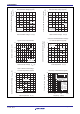
048 12 2016
0
80
60
40
20
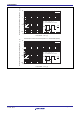
Tc= 25
°
C
150
°
C
V
CE
= 10 V
Pulse Test
Collector to Emitter Saturation Voltage
vs. Case Temparature (Typical)
−25 0257512550 100 150
Collector to Emitter Saturation Voltage
V
CE(sat)
(V)
Case Temparature Tc (
°
C)
25 A
I
C
= 50 A
V
GE
= 15 V
Pulse Test
0
Frequency Characteristics (Typical)
Collector Current I
C(RMS)
(A)
Frequency f (kHz)
1 10010 1000
Tj = 125°C
Tc = 90°C
V
CE
= 400 V
V
GE
= 15 V
Rg = 5 Ω
duty = 50%
0
Collector current wave
(Square wave)