REJ10J1428-0100 M16C R8C FoUSB/UART Debugger User’s Manual RENESAS MICROCOMPUTER Development Environment System M16C Family R8C/Tiny Series Precautions on Connecting R8C/24, R8C/25 Rev.1.00 Issued : Aug. 01, 2006 Renesas Technology www.renesas.
Active X, Microsoft, MS-DOS, Visual Basic, Visual C++, Windows and Windows NT are either registered trademarks or trademarks of Microsoft Corporation in the United States and other countries. IBM and AT are registered trademarks of International Business Machines Corporation. Intel and Pentium are registered trademarks of Intel Corporation. Adobe and Acrobat are registered trademarks of Adobe Systems Incorporated.
Table of Contents 1. Connection with User System ................................................................................................ 4 2. Prepare M16C R8C FoUSB/UART emulator debugger......................................................... 5 3. Memory Map When Using R8C UART Debugger................................................................ 17 4. Occupied Area for Monitor Program .................................................................................... 19 5.
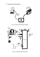
1. Connection with User System External Power Supply Host Computer RS-232C Cable + - Target Board Figure 1 Connection Example with User System Vcc Vcc LHA-0812-472K 0.1uF MAX3221EAE 2.2uF 2.2uF 15 Vcc 3 V+ 7 V- C1+ 2 C1- 4 C2+ 5 C2- 6 ROU1 9 DIODE 2.2uF 2.2uF 0.22uF 8 RI1 13 TO1 0.22uF 16 FORCEOF TIN1 11 12 FORCEON INV 10 14 GND EN 1 10 10 Vss/AVss Vcc/AVcc 12 2.
2. Prepare M16C R8C FoUSB/UART emulator debugger In the M16C R8C FoUSB/UART debugger (R8C UART debugger), connecting a PC and the target with the RS-232C can perform debugging. It is not necessary to prepare a monitor program for a user since it is bundled when installing the “M16C R8C FoUSB/UART debugger” As for the R8C/Tiny, the monitor program is automatically programmed when starting the R8C UART debugger. It is not necessary to program the monitor program with the M16C FlashStarter, etc. in advance.
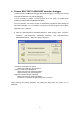
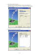
b) Select [Create a new project workspace] radio button. Push the [OK] button. c) The Project Generator starts. When a tool chain is installed, the following screen is open. • [Workspace name] Apply the workspace name newly made. “Sample” is applied as an example • [Project name] If the user wants to change the project name, apply the project name. • [CPU type] Select the applicable CPU type.
• [Tool chain] When using the tool chain, select the applicable tool chain name. When the tool chain is not used, select [None]. • [Project type] Select a project type that wants to be used. d) Next, set the tool chain. Select the tool chain version and CPU series to be used, and push the [Next] button.
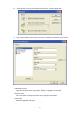
e) Next, set the RTOS. Select the RTOS and startup file type to be used, and push the “Next” button. f) Next, set the heap area, etc. Set the heap size, etc. to be used and push the [Next] button.
g) Next, set the stack area. Set the stack size and push the [Next] button. h) When the setting of the tool chain ends, the following screen is displayed. Check the M16C R8C FoUSB/UART here and push the [Next] button. If necessary, check other products.
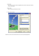
i) Next, set the configuration file name. Configurations are the build option settings (e.g., output of debug information or optimization) having their own names. The term "configuration" can also be referred to as "build configuration". j) Finally, check the file name to be generated.
k) The above settings display the file which the High-performance Embedded Workshop generates. When pushing the [OK] button, High-performance Embedded Workshop starts.
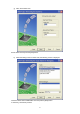
l) When double-clicking the source program, an editor starts and can be edited. m) Clicking “Build”, and “Build” or “Build All” can build after creating a program.
n) The result of a build is displayed. o) Next, connect with the target. Switching to the registered session file in which the setting uses the R8C UART debugger in advance can connect simply.
p) The Init screen is displayed. Select [Serial] radio button and push [Reference] button. q) Select the “R8C-Tiny Series”. r) Select an MCU file.
s) When pushing “OK”, a monitor program is downloaded. t) Download a user program with “Debug”, “Download” and “Download File (X30 file)”.
u) Clicking “Debug” and “Reset CPU” resets the user program. v) A cursor moves to the top of the user program and a debug can start.
3. Memory Map When Using R8C UART Debugger Figure 3 shows the Memory Map of R8C/Tiny On-chip Flash Memory (32KB version).
Figure 4 shows the Memory Map of R8C/Tiny On-chip Flash Memory (64KB version).
4. Occupied Area for Monitor Program Table 1 Occupied Area for Monitor Program ROM / RAM Occupied Area for Monitor Program 16KB / 1KB Vector FFE8h to FFEBh, FFECh to FFEFh, FFF4h to FFF7h 32KB / 2KB RAM AFFh to BFFh Flash memory 8000h to 89FFh Vector FFE8h to FFEBh, FFECh to FFEFh, FFF4h to FFF7h 48KB / 2.
5.3. Area in which user program can be downloaded As shown in Figure 3 and Figure 4, a part of RAM or Flash Memory is used for the monitor program when using the R8C UART debugger. The R8C UART debugger does not download the user program in the area which overlaps with a monitor program when a user program overlaps with a monitor program. Note that the R8C UART debugger does not perform an error output at this time. 5.4.
5.5. Limitations on SFR operation Table 4 lists the limitations on a register operation. Also, the monitor program does not operate properly when the register to which the change is disabled is changed.
5.8. Real-time operation of user program • Sampling Run (Sampling) Mode In sampling mode, the execution status of the user program will be monitored regularly when executing Go and Come. Therefore, the stop of the user program by a break can be detected. Select this mode when performing normal debug. • Free Run (free run) mode In free fun mode, the execution status of the user program will not be monitored when executing Go and Come.
5.9. Exceptional step execution • Software interrupt instruction The step execution cannot be performed continuously for the instruction internal process of the instructions (undefined instruction, overflow, BRK instruction and INT instruction) which generate the software interrupts.
5.10. Limitations on peripheral functions UART1 is used for a communication of the monitor program and the host computer. Do not use UART1 for a user program. Also, the following pins should be used for a communication with the host computer. Do not connect to other pins, etc. • R8C/24,25 Groups TxD1 (28pin), RxD1 (29pin) 5.11. Limitations on flag register When operating the flag register on the user program, execute the FSET instruction and FCLR instruction not to change the debug flag (D flag). 5.12.
M16C R8C FoUSB/ART Debugger User’s Manual Precautions on Connecting R8C/24, R8C/25 Publication Date Rev.1.00 Aug 01, 2006 Published by: Sales Strategic Planning Div. Renesas Technology Corp. Edited by: Renesas Solutions Corp. © 2006. Renesas Technology Corp. and Renesas Solutions Corp., All rights reserved. Printed in Japan.
M16C R8C FoUSB/UART Debugger User’s Manual Precautions on Connecting R8C/24, R8C/25