
Technical information


R8C/14 Group, R8C/15 Group 13. Timers
Rev.2.10 Jan 19, 2006 Page 109 of 253
REJ09B0164-0210
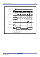
Figure 13.19 TZMR and PUM Registers in Programmable One-Shot Generation Mode
Timer Z Waveform Output Control Register
Symbol Address After Reset
PUM
0084h 00h
Bit Symbol Bit Name Function RW
INT0
_
____
Pin One-shot Trigger 0 : INT0
_
____
pin one-shot trigger disabled
Control Bit
(1)
1 : INT0
_
____
pin one-shot trigger enabled
INT0
_
____
Pin One-shot Trigger
Polarity Select Bit
(2)
NOTES :
1.
2.
b3 b2
INOSTG
b1 b0
0
—
(b4-b0)
00
0 : Outputs one-shot pulse “H”
Outputs “L” w hen the timer is stopped
1 : Outputs one-shot pulse “L”
Outputs “H” w hen the timer is stopped
b7 b6 b5 b4
00
RW
INOSEG RW
RW
TZOPL RW
0 : Falling edge trigger
1 : Rising edge trigger
Reserved Bit Set to “0”
Timer Z Output Level Latch
Set the INOSTG bit to “1” after the INT0EN bit in the INTEN register and the INOSEG bit in the PUM
The INOSEG bit is enabled only w hen the INT0PL bit in the INTEN register is set to “0” (one edge).
INT0F1 bits in the INT0F register. Set the INOSTG bit to “0” (INT0
_
____
pin one-shot trigger disabled) after the
TZS bit in the TZMR register is set to “0” (count stop).
register are set. When setting the INOSTG bit to “1” (INT0
_
____
pin one-shot trigger enabled), set the INT0F0 to
Timer Z Mode Register
Symbol Address After Reset
TZMR
0080h 00h
Bit Symbol Bit Name Function RW
NOTES :
1.
2. Refer to
20.4.3 Timer Z
for precautions on the TZS bit.
b0
When the TZS bit is set to “1” (count start), The count value is w ritten to the reload register only. When the TZS bit is
set to “0” (count stop), The count value is w ritten to both reload register and counter.
TZWC
TZS
Timer Z Write Control Bit Set to “1” in programmable one-shot generation
mode
(1)
0
b3 b2 b1
0
TZMOD1
b7 b6 b5 b4
110
Timer Z Count Start Flag
(2)
0 : Stops counting
1 : Starts counting
0
—
(b3-b0)
Reserved Bit
RW
RW
0
Set to “0”
RW
Timer Z Operating Mode Bit
b5 b4
1 0 : Programmable one-shot generation mode
RW
TZMOD0 RW