
Datasheet


Rev.1.20 Jan 27, 2006 page 7 of 27
REJ03B0069-0120
R8C/13 Group 2. Central Processing Unit (CPU)
2. Central Processing Unit (CPU)
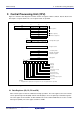
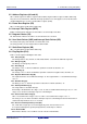
Figure 2.1 shows the CPU Register. The CPU contains 13 registers. Of these, R0, R1, R2, R3, A0, A1 and
FB comprise a register bank. Two sets of register banks are provided.
2.1 Data Registers (R0, R1, R2 and R3)
R0 is a 16-bit register for transfer, arithmetic and logic operations. The same applies to R1 to R3. The R0
can be split into high-order bit (R0H) and low-order bit (R0L) to be used separately as 8-bit data registers.
The same applies to R1H and R1L as R0H and R0L. R2 can be combined with R0 to be used as a 32-bit
data register (R2R0). The same applies to R3R1 as R2R0.
D
a
t
a
r
e
g
i
s
t
e
r
s
(
1
)
Address registers
(1)
F
r
a
m
e
b
a
s
e
r
e
g
i
s
t
e
r
s
(
1
)
P
r
o
g
r
a
m
c
o
u
n
t
e
r
I
n
t
e
r
r
u
p
t
t
a
b
l
e
r
e
g
i
s
t
e
r
User stack pointer
I
n
t
e
r
r
u
p
t
s
t
a
c
k
p
o
i
n
t
e
r
Static base register
F
l
a
g
r
e
g
i
s
t
e
r
N
O
T
E
S
:
1
.
A
r
e
g
i
s
t
e
r
b
a
n
k
c
o
m
p
r
i
s
e
s
t
h
e
s
e
r
e
g
i
s
t
e
r
s
.
T
w
o
s
e
t
s
o
f
r
e
g
i
s
t
e
r
b
a
n
k
s
a
r
e
p
r
o
v
i
d
e
d
R0H(High-order of R0)
b
1
5
b
8
b
7
b0
R
3
I
N
T
B
H
USP
I
S
P
SB
CDZSBOIU
I
P
L
R
0
L
(
L
o
w
-
o
r
d
e
r
o
f
R
0
)
R1H(High-order of R1)
R1L(Low-order of R1)
R
2
b
3
1
R3
R2
A1
A0
F
B
b
1
9
I
N
T
B
L
b
1
5
b0
P
C
b
1
9
b0
b15 b0
F
L
G
b
1
5
b0
b
1
5
b0 b
7
b8
Reserved bit
Carry flag
Debug flag
Zero flag
Sign flag
Register bank select flag
Overflow flag
Interrupt enable flag
Stack pointer select flag
Reserved bit
Processor interrupt priority level
The 4-high order bits of INTB are INTBH and
the 16-low bits of INTB are INTBL.
Figure 2.1 CPU Register