
Datasheet


RL78/L12
CHAPTER 31 ELECTRICAL SPECIFICATIONS (G: TA = -40 to +105°C)
R01UH0330EJ0200 Rev.2.00 956
Dec 13, 2013
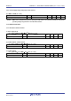
31.6.5 Power supply voltage rising slope characteristics
(T
A = −40 to +105°C, VSS = 0 V)
Parameter Symbol Conditions MIN. TYP. MAX. Unit
Power supply voltage rising slope SVDD 54 V/ms
Caution Make sure to keep the internal reset state by the LVD circuit or an external reset until VDD reaches the
operating voltage range shown in 31.4 AC Characteristics.
31.7 LCD Characteristics
31.7.1 Resistance division method
(1) Static display mode
(T
A = −40 to +105°C, VL4 (MIN.) ≤ VDD
Note
≤ 5.5 V, VSS = 0 V)
Parameter Symbol Conditions MIN. TYP. MAX. Unit
LCD drive voltage VL4 2.0 VDD V
Note Must be 2.4 V or higher.
(2) 1/2 bias method, 1/4 bias method
(T
A = −40 to +105°C, VL4 (MIN.) ≤ VDD ≤ 5.5 V, VSS = 0 V)
Parameter Symbol Conditions MIN. TYP. MAX. Unit
LCD drive voltage VL4 2.7 VDD V
(3) 1/3 bias method
(T
A = −40 to +105°C, VL4 (MIN.) ≤ VDD ≤ 5.5 V, VSS = 0 V)
Parameter Symbol Conditions MIN. TYP. MAX. Unit
LCD drive voltage VL4 2.5 VDD V