
Datasheet


RL78/L12 CHAPTER 14 LCD CONTROLLER/DRIVER
R01UH0330EJ0200 Rev.2.00 639
Dec 13, 2013
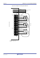
Figure 14-25 shows the common signal waveforms, and Figure 14-26 shows the voltages and phases of the common
and segment signals.
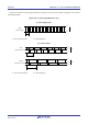
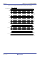
Figure 14-25. Common Signal Waveforms (1/2)
(a) Static display mode
COMn
(Static display)
T
F
= T
V
L4
V
SS
V
LCD
T: One LCD clock period TF: Frame frequency
(b) 1/2 bias method
COMn
(Two-time-slice mode)
T
F
= 2 T
V
L4
V
SS
V
LCD
V
L2
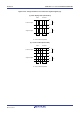
COMn
(Three-time-slice mode)
T
F
= 3 T
V
L4
V
SS
V
LCD
V
L2
T: One LCD clock period TF: Frame frequency