
Datasheet


RL78/L12 CHAPTER 12 SERIAL ARRAY UNIT
R01UH0330EJ0200 Rev.2.00 388
Dec 13, 2013
12.3.1 Peripheral enable register 0 (PER0)
PER0 is used to enable or disable supplying the clock to the peripheral hardware. Clock supply to a hardware macro
that is not used is stopped in order to reduce the power consumption and noise.
When serial array unit is used, be sure to set bit 2 (SAU0EN) of this register to 1.
The PER0 register can be set by a 1-bit or 8-bit memory manipulation instruction.
Reset signal generation clears the PER0 register to 00H.
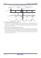
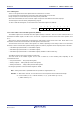
Figure 12-3. Format of Peripheral Enable Register 0 (PER0)
Address: F00F0H After reset: 00H R/W
Symbol <7> 6 <5> <4> 3 <2> 1 <0>
PER0 RTCEN 0 ADCEN IICA0EN 0 SAU0EN 0 TAU0EN
SAU0EN Control of serial array unit input clock supply
0
Stops supply of input clock.
• SFR used by serial array unit cannot be written.
• Serial array unit is in the reset status.
1
Enables input clock supply.
• SFR used by serial array unit can be read/written.
Cautions 1. When setting serial array unit, be sure to first set the following registers with the
SAU0EN bit set to 1. If SAU0EN = 0, control registers of serial array unit m become
default values and writing to them is ignored (except for the input switch control register
(ISC), noise filter enable register 0 (NFEN0), port input mode register 1 (PIM1), port
output mode register 1 (POM1), LCD port function registers 0, 3 (PFSEG0, PFSEG3), port
mode register 1 (PM1), and port register 1 (P1)).
• Serial clock select register m (SPSm)
• Serial mode register mn (SMRmn)
• Serial communication operation setting register mn (SCRmn)
• Serial data register mn (SDRmn)
• Serial flag clear trigger register mn (SIRmn)
• Serial status register mn (SSRmn)
• Serial channel start register m (SSm)
• Serial channel stop register m (STm)
• Serial channel enable status register m (SEm)
• Serial output enable register m (SOEm)
• Serial output level register m (SOLm)
• Serial output register m (SOm)
• Serial standby control register m (SSCm)
2. Be sure to clear bits 1, 3, 6 to “0”.
<R>