
Datasheet


RL78/L12 CHAPTER 9 CLOCK OUTPUT/BUZZER OUTPUT CONTROLLER
R01UH0330EJ0200 Rev.2.00 324
Dec 13, 2013
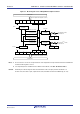
Notes 1. Use the output clock within a range of 16 MHz. Furthermore, when using the output clock
at 2.7 V ≤ VDD < 4.0 V, can be use it within 8 MHz only. See 30.4 or 31.4 AC
Characteristics for details.
2. Do not select f
SUB as the clock output from the clock output/buzzer output controller when
the WUTMMCK0 bit of the OSMC register is set to 1.
Cautions 1. Change the output clock after disabling clock output (PCLOEn = 0).
2. To shift to STOP mode when the main system clock is selected (CSELn = 0), set
PCLOEn = 0 before executing the STOP instruction. When the subsystem clock is
selected (CSELn = 1), PCLOEn = 1 can be set because the clock can be output
while the RTCLPC bit of the subsystem clock supply mode control (OSMC)
register is set to 0 and moreover while STOP mode is set.
3. It is not possible to output the subsystem clock (f
SUB) from the PCLBUZn pin while
the RTCLPC bit of the subsystem clock supply mode control register (OSMC) is
set to 1 and moreover while HALT mode is set with the subsystem clock (f
SUB)
selected as CPU clock.
Remarks 1. n = 0, 1
2. f
MAIN: Main system clock frequency
fSUB: Subsystem clock frequency
<R>
<R>