
Datasheet


RL78/L12 APPENDIX A REVISION HISTORY
R01UH0330EJ0200 Rev.2.00 983
Dec 13, 2013
(5/10)
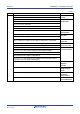
Edition
Description Chapter
Rev.1.00
Modification of description in 12.5.3 Master transmission/reception
CHAPTER 12
SERIAL ARRAY UNIT
Modification of note to 12.5.4 Slave transmission, 12.5.5 Slave reception, 12.5.6 Slave
transmission/reception
Modification of description in 12.5.7 SNOOZE mode function
Modification of caution in Figures 12-70 and 12-72
Modification of description in 12.6.1 UART transmission and 12.6.2 UART reception
Modification of Figure 12-80, 82 (flow chart)
Modification of Figure 12-83 (Example of Contents of Registers).
Modification of Figure 12-88. Flowchart of UART Reception
Addition of description in 12.6.3 SNOOZE mode function
Modification of note and caution in Figure 12-89. Timing Chart of SNOOZE Mode Operation
(Normal operation mode)
Modification of caution in Figure 12-90. Timing Chart of SNOOZE Mode Operation
(Abnormal Operation <1>)
Modification of Figure 12-91. Flowchart of SNOOZE Mode Operation (Normal
Operation/Abnormal Operation <1>)
Modification of Figure 12-93. Flowchart of SNOOZE Mode Operation (Abnormal Operation <2>)
Modification of description and note in 12.7.1 LIN transmission and 12.7.2 LIN reception
Modification of Figure 12-97. Master Transmission Operation of LIN
Modification of Figure 12-98. Flowchart for LIN Transmission
Modification of Figure 12-99. Reception Operation of LIN
Modification of Figure 12-100. Flowchart for LIN Reception
Modification of Figure 13-9. Format of IICA Control Register n1 (IICCTLn1) (2/2)
CHAPTER 13
SERIAL INTERFACE
IICA
Modification of 13.5.13 Wakeup function
Modification of 13.5.17 (2) (d) Start ~ Address ~ Data ~ Start ~ Address ~ Data ~ Stop
Modification of 13.5.17 (3) (d) Start ~ Code ~ Data ~ Start ~ Address ~ Data ~ Stop
Modification of Figure 13-9. Format of IICA Control Register n1 (IICCTLn1) (2/2)
Modification of 13.5.13 Wakeup function
Modification of 13.5.17 (2) (d) Start ~ Address ~ Data ~ Start ~ Address ~ Data ~ Stop
Modification of 13.5.17 (3) (d) Start ~ Code ~ Data ~ Start ~ Address ~ Data ~ Stop
Modification of Table 14-1. Number of LCD Display Function Pins of Each Product
CHAPTER 14
LCD
CONTROLLER/DRIVER
Modification of Table 14-4. Combinations of Display Waveform, Time Slices, and Bias Method
Addition of notes 1, 3 to Figure 14-4. Format of LCD Mode Register 1 (LCDM1) (1/2)
Modification of note and caution 1 in Figure 14-4. Format of LCD Mode Register 1 (LCDM1) (2/2)