
Datasheet

RL78/G12 1. OUTLINE
R01DS0193EJ0200 Rev.2.00
Sep 06, 2013
Page 8 of 106
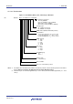
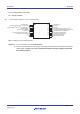
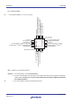
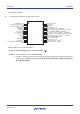
1.4.2 24-pin products
• 24-pin plastic HWQFN (4 × 4 mm, 0.5 mm pitch)
1 2 3 4 5 6
12
11
10
9
8
7
18 17 16 15 14 13
19
20
21
22
23
24
P61/KR5/SDAA00/(RxD0)
P60/KR4/SCLA0/(TxD0)
P03/KR9
P02/KR8/(SCK01)
Note
/(SCL01)
Note
P01/KR7/(SO01)
Note
/(SDA01)
Note
P00/KR6/(SI01)
Note
P22/ANI2
P21/ANI1/AV
REFM
P20/ANI0/AV
REFP
P42/ANI21/SCK01
Note
/SCL01
Note
/TI03/TO03
P41/ANI22/SO01
Note
/SDA01
Note
/TI02/TO02/INTP1
P40/KR0/TOOL0
INDEX MARK
exposed die pad
V
DD
V
SS
P122/KR2/X2/EXCLK/(TI02)/(INTP2)
P121/KR3/X1/(TI03)/(INTP3)
P137/INTP0
P125/KR1/SI01
Note
/RESET
P14/ANO20/TI01/ONTP3
P13/ANO19/TI00/ONTP2
P11/ANI17/SI00/SDA00
Note
/TOOLRxD
P12/ANI18/SO00/TxD0/TOOLTxD
P10/ANI16/PCLBUZ0/SCK00/SCL00
Note
P23/ANI3
Note Provided only in the R5F102 products.
Remarks 1. For pin identification, see 1.5 Pin Identification.
2. Functions in parentheses in the above figure can be assigned via settings in the peripheral I/O redirection
register (PIOR). See Figure 4-8 Format of Peripheral I/O Redirection Register (PIOR) in the RL78/G12
User’s Manual Hardware.
3. It is recommended to connect an exposed die pad to Vss.
<R>
<R>