
Datasheet


RL78/G12 3. ELECTRICAL SPECIFICATIONS (G: T
A = −40 to +105°C)
R01DS0193EJ0200 Rev.2.00
Sep 06, 2013
Page 101 of 106
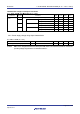
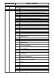
LVD detection voltage of interrupt & reset mode
(T
A = −40 to +105°C, VPDR ≤ VDD ≤ 5.5 V, VSS = 0 V)
Parameter Symbol Conditions MIN. TYP. MAX. Unit
Interrupt and reset
mode
V
LVDD0 VPOC2, VPOC1, VPOC1 = 0, 1, 1, falling reset voltage 2.64 2.75 2.86 V
VLVDD1
LVIS1, LVIS0 = 1, 0
Rising reset release voltage 2.81 2.92 3.03 V
Falling interrupt voltage 2.75 2.86 2.97 V
VLVDD2
LVIS1, LVIS0 = 0, 1
Rising reset release voltage 2.90 3.02 3.14 V
Falling interrupt voltage 2.85 2.96 3.07 V
VLVDD3
LVIS1, LVIS0 = 0, 0
Rising reset release voltage 3.90 4.06 4.22 V
Falling interrupt voltage 3.83 3.98 4.13 V
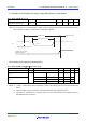
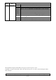
3.6.5 Power supply voltage rising slope characteristics
(T
A = −40 to +105°C, VSS = 0 V)
Parameter Symbol Conditions MIN. TYP. MAX. Unit
Power supply voltage rising slope SVDD 54 V/ms
Caution Make sure to keep the internal reset state by the LVD circuit or an external reset until VDD reaches the
operating voltage range shown in 3.4 AC Characteristics.