
Datasheet

RL78/G12 3. ELECTRICAL SPECIFICATIONS (G: T
A = −40 to +105°C)
R01DS0193EJ0200 Rev.2.00
Sep 06, 2013
Page 103 of 106
3.9 Dedicated Flash Memory Programmer Communication (UART)
(TA = −40 to +105°C, 2.4 V ≤ VDD ≤ 5.5 V, VSS = 0 V)
Parameter Symbol Conditions MIN. TYP. MAX. Unit
Transfer rate During serial programming 115,200 1,000,000 bps
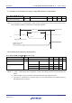
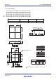
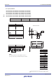
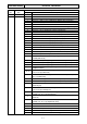
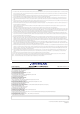
3.10 Timing of Entry to Flash Memory Programming Modes
(TA = −40 to +105°C, 2.4 V ≤ VDD ≤ 5.5 V, VSS = 0 V)
Parameter Symbol Conditions MIN. TYP. MAX. Unit
Time to complete the communication for the initial
setting after the external reset is released
t
SUINIT
POR and LVD reset are released
before external release
100 ms
Time to release the external reset after the TOOL0
pin is set to the low level
t
SU
POR and LVD reset are released
before external release
10
μ
s
Time to hold the TOOL0 pin at the low level after the
external reset is released
(excluding the processing time of the firmware to
control the flash memory)
t
HD
POR and LVD reset are released
before external release
1 ms
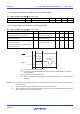
RESET
TOOL0
<1>
<2>
<3>
t
SUINIT
tHD + software
processing
time
1-byte data for
setting mode
t
SU
<4>
<1> The low level is input to the TOOL0 pin.
<2> The external reset is released (POR and LVD reset must be released before the external
reset is released.).
<3> The TOOL0 pin is set to the high level.
<4> Setting of the flash memory programming mode by UART reception and complete the baud
rate setting.
Remark t
SUINIT: Communication for the initial setting must be completed within 100 ms after the external reset is released
during this period.
tSU: Time to release the external reset after the TOOL0 pin is set to the low level
t
HD: Time to hold the TOOL0 pin at the low level after the external reset is released (excluding the processing
time of the firmware to control the flash memory)