
Datasheet

RL78/G12 2. ELECTRICAL SPECIFICATIONS (A, D: T
A = −40 to +85°C)
R01DS0193EJ0200 Rev.2.00
Sep 06, 2013
Page 40 of 106
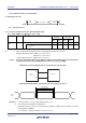
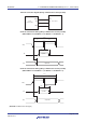
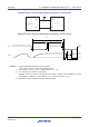
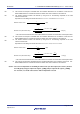
UART mode connection diagram (during communication at different potential)
RL78
microcontroller
TxDq
RxDq
Rx
Tx
User's device
Vb
Rb
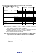
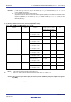
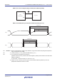
UART mode bit width (during communication at different potential) (reference)
TxDq
RxDq
Baud rate error tolerance
High-/Low-bit width
1/Transfer rate
Baud rate error tolerance
High-bit width
Low-bit width
1/Transfer rate
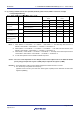
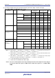
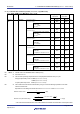
Remarks 1. R
b[Ω]: Communication line (TxDq) pull-up resistance, Cb[F]: Communication line (TxDq) load capacitance,
V
b[V]: Communication line voltage
2. q: UART number (q = 0 to 2), g: PIM and POM number (g = 0, 1)
3. f
MCK: Serial array unit operation clock frequency
(Operation clock to be set by the serial clock select register m (SPSm) and the CKSmn bit of serial mode
register mn (SMRmn).
m: Unit number, n: Channel number (mn = 00 to 03, 10, 11))
4. UART0 of the 20- and 24-pin products supports communication at different potential only when the
peripheral I/O redirection function is not used.
<R>
<R>
<R>