
Datasheet


RL78/G13 2. ELECTRICAL SPECIFICATIONS (A, D: T
A = -40 to +85°C)
Page 55 of 194R01DS0131EJ0310 Rev.3.10
Nov 15, 2013
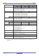
2.1 Absolute Maximum Ratings
Absolute Maximum Ratings (T
A = 25°C) (1/2)
Parameter Symbols Conditions Ratings Unit
Supply voltage VDD −0.5 to +6.5 V
EVDD0, EVDD1 EVDD0 = EVDD1 −0.5 to +6.5 V
EVSS0, EVSS1 EVSS0 = EVSS1 −0.5 to +0.3 V
REGC pin input voltage VIREGC REGC −0.3 to +2.8
and −0.3 to VDD +0.3
Note 1
V
Input voltage VI1 P00 to P07, P10 to P17, P30 to P37, P40 to P47,
P50 to P57, P64 to P67, P70 to P77, P80 to P87,
P90 to P97, P100 to P106, P110 to P117, P120,
P125 to P127, P140 to P147
−0.3 to EV
DD0 +0.3
and −0.3 to V
DD +0.3
Note 2
V
VI2 P60 to P63 (N-ch open-drain) −0.3 to +6.5 V
VI3 P20 to P27, P121 to P124, P137, P150 to P156,
EXCLK, EXCLKS, RESET
−0.3 to V
DD +0.3
Note 2
V
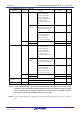
Output voltage VO1 P00 to P07, P10 to P17, P30 to P37, P40 to P47,
P50 to P57, P60 to P67, P70 to P77, P80 to P87,
P90 to P97, P100 to P106, P110 to P117, P120,
P125 to P127, P130, P140 to P147
−0.3 to EVDD0 +0.3
and −0.3 to V
DD +0.3
Note 2
V
VO2 P20 to P27, P150 to P156
−0.3 to V
DD +0.3
Note 2
V
Analog input voltage VAI1 ANI16 to ANI26 −0.3 to EVDD0 +0.3
and −0.3 to AVREF(+) +0.3
Notes 2, 3
V
VAI2 ANI0 to ANI14 −0.3 to VDD +0.3
and −0.3 to AVREF(+) +0.3
Notes 2, 3
V
Notes 1. Connect the REGC pin to Vss via a capacitor (0.47 to 1
μ
F). This value regulates the absolute
maximum rating of the REGC pin. Do not use this pin with voltage applied to it.
2. Must be 6.5 V or lower.
3. Do not exceed AV
REF(+) + 0.3 V in case of A/D conversion target pin.
Caution Product quality may suffer if the absolute maximum rating is exceeded even momentarily for any
parameter. That is, the absolute maximum ratings are rated values at which the product is on the
verge of suffering physical damage, and therefore the product must be used under conditions
that ensure that the absolute maximum ratings are not exceeded.
Remarks 1. Unless specified otherwise, the characteristics of alternate-function pins are the same as those of the
port pins.
2. AVREF (+) : + side reference voltage of the A/D converter.
3. V
SS : Reference voltage