
Datasheet


RL78/G13 1. OUTLINE
Page 20 of 194R01DS0131EJ0310 Rev.3.10
Nov 15, 2013
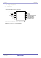
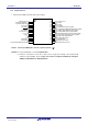
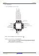
1.3.5 32-pin products
• 32-pin plastic HWQFN (5 × 5 mm, 0.5 mm pitch)
16
15
14
13
12
11
10
9
25
26
27
28
29
30
31
32
24 23 22 21 20 19 18 17
1 2 3 4 5 6 7 8
P147/ANI18
P23/ANI3
P22/ANI2
P21/ANI1/AV
REFM
P20/ANI0/AV
REFP
P01/ANI16/TO00/RxD1
P00/ANI17/TI00/TxD1
P120/ANI19
P51/INTP2/SO11
P50/INTP1/SI11/SDA11
P30/INTP3/SCK11/SCL11
P70
P31/TI03/TO03/INTP4/PCLBUZ0
P62
P61/SDAA0
P60/SCLA0
exposed die pad
P10/SCK00/SCL00/(TI07)/(TO07)
P11/SI00/RxD0/TOOLRxD/SDA00/(TI06)/(TO06)
P12/SO00/TxD0/TOOLTxD/(TI05)/(TO05)
P13/TxD2/SO20/(SDAA0)/(TI04)/(TO04)
P14/RxD2/SI20/SDA20/(SCLA0)/(TI03)/(TO03)
P15/PCLBUZ1/SCK20/SCL20/(TI02)/(TO02)
P16/TI01/TO01/INTP5/(RXD0)
P17/TI02/TO02/(TXD0)
P40/TOOL0
RESET
P137/INTP0
P122/X2/EXCLK
P121/X1
REGC
V
SS
V
DD
INDEX MARK
Caution Connect the REGC pin to Vss via a capacitor (0.47 to 1
μ
F).
Remarks 1. For pin identification, see 1.4 Pin Identification.
2. Functions in parentheses in the above figure can be assigned via settings in the peripheral I/O
redirection register (PIOR). Refer to Figure 4-8 Format of Peripheral I/O Redirection Register
(PIOR)
in the RL78/G13 User’s Manual Hardware
.
3. It is recommended to connect an exposed die pad to Vss.