
Datasheet


Section 16 I2C Bus Interface 2 (IIC2)
Page 962 of 1384 R01UH0310EJ0500 Rev. 5.00
Sep 25, 2012
H8S/2426, H8S/2426R, H8S/2424 Group
16.3.2 I
2
C Bus Control Register B (ICCRB)
ICCRB is an 8-bit readable/writable register that issues start/stop conditions, manipulates the SDA
pin, monitors the SCL pin, and controls reset in I
2
C control.
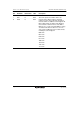
Bit Bit Name Initial Value R/W Description
7 BBSY 0 R/W Bus Busy
This bit enables to confirm whether the I
2
C bus is
occupied or released and to issue start and stop
conditions in master mode. This bit is set to 1
when the SDA level changes from high to low
under the condition of SCL = high, assuming that
the start condition has been issued. This bit is
cleared to 0 when the SDA level changes from low
to high under the condition of SCL = high,
assuming that the stop condition has been issued.
Write 1 to BBSY and 0 to SCP to issue a start
condition. Follow this procedure when also re-
transmitting a start condition. Write 0 to BBSY and
0 to SCP to issue a stop condition. To issue a
start/stop condition, use the MOV instruction.
6 SCP 1 R/W Start Condition/Stop Condition Prohibit
The SCP bit controls the issue of start/stop
conditions in master mode.
To issue a start condition, write 1 in BBSY and 0
in SCP. A retransmit start condition is issued in
the same way. To issue a stop condition, write 0 in
BBSY and 0 in SCP. This bit is always read as 1.
If 1 is written, the data is not stored.
5 SDAO 1 R This bit monitors SDA output level. When reading
and SDA0 is 1, the SDA pin outputs high. When
reading and SDA0 is 0, the SDA pin outputs low.
The write value should always be 1.
4 ⎯ 1 R/W Reserved
The write value should always be 1.
3 SCLO 1 R This bit monitors SCL output level. When reading
and SCLO is 1, the SCL pin outputs high. When
reading and SCLO is 0, the SCL pin outputs low.
2 ⎯ 1 ⎯ Reserved
This bit is always read as 1.