
Datasheet


Section 16 I2C Bus Interface 2 (IIC2)
Page 960 of 1384 R01UH0310EJ0500 Rev. 5.00
Sep 25, 2012
H8S/2426, H8S/2426R, H8S/2424 Group
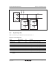
16.3.1 I
2
C Bus Control Register A (ICCRA)
ICCRA is an 8-bit readable/writable register that enables or disables the I
2
C bus interface, controls
transmission or reception, and selects master or slave mode, transmission or reception, and
transfer clock frequency in master mode.
Bit Bit Name Initial Value R/W Description
7 ICE 0 R/W I
2
C Bus Interface Enable
0: Disables SCL/SDA outputs. (Inputs to SCL/SDA
are available.)
1: This module is enabled for transfer operations.
(SCL and SDA pins are bus drive state.)
6 RCVD 0 R/W Reception Disable
This bit enables or disables the next operation
when TRS is 0 and ICDRR is read.
0: Enables next reception.
1: Disables next reception.
5
4
MST
TRS
0
0
R/W
R/W
Master/Slave Select
Transmit/Receive Select
When arbitration is lost in master mode, MST and
TRS are both reset by hardware, causing a
transition to slave receive mode. Modification of
the TRS bit should be made between transfer
frames. In addition, TRS is set to 1 automatically
in slave receive mode if the seventh bit of the start
condition matches the slave address set in SAR
and the eighth bit is set to 1.
Operating modes are described below according
to MST and TRS combination.
00: Slave receive mode
01: Slave transmit mode
10: Master receive mode
11: Master transmit mode
3
2
1
0
CKS3
CKS2
CKS1
CKS0
0
0
0
0
R/W
R/W
R/W
R/W
Transfer Clock Select 3 to 0
In the master mode, these bits should be set
according to the necessary transfer rate (see table
16.2). In the slave mode, they are used to secure
the data setup time in transmit mode. The data
setup time is 10 tcyc if CKS3 is cleared to 0 and
20 tcyc if CKS3 is set to 1.