
Datasheet


Section 16 I2C Bus Interface 2 (IIC2)
R01UH0310EJ0500 Rev. 5.00 Page 955 of 1384
Sep 25, 2012
H8S/2426, H8S/2426R, H8S/2424 Group
Section 16 I
2
C Bus Interface 2 (IIC2)
This LSI has a four-channel I
2
C bus interface.
The I
2
C bus interface conforms to and provides a subset of the NXP I
2
C bus (inter-IC bus)
interface functions (Rev. 0.3) for standard-mode and fast-mode. The register configuration that
controls the I
2
C bus differs partly from the NXP configuration, however.
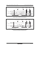
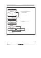
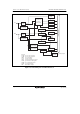
Figure 16.1 shows a block diagram of the I
2
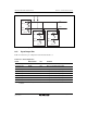
C bus interface 2. Figure 16.2 shows an example of
I/O pin connections to external circuits.
16.1 Features
• Continuous transmission/reception
Since the shift register, transmit data register, and receive data register are independent from
each other, the continuous transmission/reception can be performed.
• Start and stop conditions generated automatically in master mode
• Selection of acknowledge output levels when receiving
• Automatic loading of acknowledge bit when transmitting
• Bit synchronization/wait function
In master mode, the state of SCL is monitored per bit, and the timing is synchronized
automatically. If transmission/reception is not yet possible, set the SCL to low until
preparations are completed.
• Six interrupt sources
Transmit-data-empty (including slave-address match), transmit-end, receive-data-full
(including slave-address match), arbitration lost, NACK detection, and stop condition
detection
• Direct bus drive
Two pins, SCL and SDA pins function as NMOS open-drain outputs.