
Datasheet

Section 15 Serial Communication Interface (SCI, IrDA)
Page 950 of 1384 R01UH0310EJ0500 Rev. 5.00
Sep 25, 2012
H8S/2426, H8S/2426R, H8S/2424 Group
15.10.7 Operation in Case of Mode Transition
• Transmission
Operation should be stopped (by clearing TE, TIE, and TEIE to 0) before setting the module
stop state or making a transition to software standby mode. TSR, TDR, and SSR are reset. The
output pin states in the module stop state or software standby mode depend on the port
settings, and become high-level output after the relevant mode is cleared. If a transition is
made during transmission, the data being transmitted will be undefined.
When transmitting without changing the transmit mode after the relevant mode is cleared,
transmission can be started by setting TE to 1 again, and performing the following sequence:
SSR read → TDR write → TDRE clearance. To transmit with a different transmit mode after
clearing the relevant mode, the procedure must be started again from initialization.
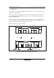
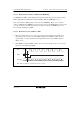
Figure 15.36 shows a sample flowchart for mode transition during transmission. Port pin states
during mode transition are shown in figures 15.37 and 15.38.
Operation should also be stopped (by clearing TE, TIE, and TEIE to 0) before making a
transition from transmission by DTC transfer to module stop state setting or software standby
mode transition. To perform transmission with the DTC after the relevant mode is cleared,
setting TE and TIE to 1 will set the TXI flag and start DTC transmission.
• Reception
Receive operation should be stopped (by clearing RE to 0) before setting the module stop state
or making a transition to software standby mode. RSR, RDR, and SSR are reset. If a transition
is made during reception, the data being received will be invalid.
To continue receiving without changing the reception mode after the relevant mode is cleared,
set RE to 1 before starting reception. To receive with a different receive mode, the procedure
must be started again from initialization.
Figure 15.39 shows a sample flowchart for mode transition during reception.