
Datasheet

Section 15 Serial Communication Interface (SCI, IrDA)
Page 948 of 1384 R01UH0310EJ0500 Rev. 5.00
Sep 25, 2012
H8S/2426, H8S/2426R, H8S/2424 Group
15.10 Usage Notes
15.10.1 Module Stop Function Setting
SCI operation can be disabled or enabled using the module stop control register. The initial setting
is for SCI operation to be halted. Register access is enabled by clearing the module stop state. For
details, refer to section 23, Power-Down Modes.
15.10.2 Break Detection and Processing
When framing error detection is performed, a break can be detected by reading the RxD pin value
directly. In a break, the input from the RxD pin becomes all 0s, and so the FER flag is set, and the
PER flag may also be set. Note that, since the SCI continues the receive operation after receiving a
break, even if the FER flag is cleared to 0, it will be set to 1 again.
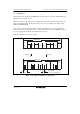
15.10.3 Mark State and Break Sending
When TE is 0, the TxD pin is used as an I/O port whose direction (input or output) and level are
determined by DR and DDR. This can be used to set the TxD pin to mark state or send a break
during serial data transmission. To maintain the communication line at mark state until TE is set to
1, set both DDR and DR to 1. Since TE is cleared to 0 at this point, the TxD pin becomes an I/O
port, and 1 is output from the TxD pin. To send a break during serial transmission, first set DDR
to 1 and clear DR to 0, and then clear TE to 0. When TE is cleared to 0, the transmitter is
initialized regardless of the current transmission state, the TxD pin becomes an I/O port, and 0 is
output from the TxD pin.
15.10.4 Receive Error Flags and Transmit Operations (Clocked Synchronous Mode Only)
Transmission cannot be started when a receive error flag (ORER, PER, or FER) is set to 1, even if
the TDRE flag is cleared to 0. Be sure to clear the receive error flags to 0 before starting
transmission. Note also that receive error flags cannot be cleared to 0 even if the RE bit is cleared
to 0.