
Datasheet


Section 15 Serial Communication Interface (SCI, IrDA)
R01UH0310EJ0500 Rev. 5.00 Page 927 of 1384
Sep 25, 2012
H8S/2426, H8S/2426R, H8S/2424 Group
15.7 Operation in Smart Card Interface Mode
The SCI supports an IC card (Smart Card) interface conforming to ISO/IEC 7816-3 (Identification
Card) as a serial communication interface extension function. Switching between the normal serial
communication interface and the Smart Card interface is carried out by means of a register setting.
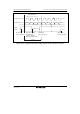
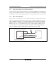
15.7.1 Pin Connection Example
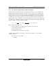
Figure 15.21 shows an example of connection with the Smart Card. In communication with an IC
card, since both transmission and reception are carried out on a single data transmission line, the
TxD pin and RxD pin should be connected with the LSI pin. The data transmission line should be
pulled up to the V
CC
power supply with a resistor. If an IC card is not connected, and the TE and
RE bits are both set to 1, closed transmission/reception is possible, enabling self-diagnosis to be
carried out. When the clock generated on the SCI is used by an IC card, the SCK pin output is
input to the CLK pin of the IC card. This LSI port output is used as the reset signal.
TxD
RxD
This LSI
V
CC
I/O
Connected equipment
IC card
Data line
CLK
RST
SCK
Rx (port)
Clock line
Reset line
Figure 15.21 Schematic Diagram of Smart Card Interface Pin Connections