
Datasheet


Section 15 Serial Communication Interface (SCI, IrDA)
Page 926 of 1384 R01UH0310EJ0500 Rev. 5.00
Sep 25, 2012
H8S/2426, H8S/2426R, H8S/2424 Group
Yes
<End>
[1]
No
Initialization
Start of transmission/reception
[5]
Error handling
[3]
Read receive data in RDR, and
clear RDRF flag in SSR to 0
No
Yes
ORER = 1?
All data received?
[2]
Read TDRE flag in SSR
No
Yes
TDRE = 1?
Write transmit data to TDR and
clear TDRE flag in SSR to 0
No
Yes
RDRF = 1?
Read ORER flag in SSR
[4]
Read RDRF flag in SSR
Clear TE and RE bits in SCR to 0
Note:
When switching from transmit or receive operation to simultaneous
transmit and receive operations, first clear the TE and RE bits to 0,
then set both these bits to 1 simultaneously.
[1]
[2]
[3]
[4]
[5]
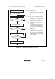
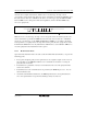
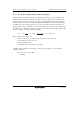
SCI initialization:
The TxD pin is designated as the
transmit data output pin, and the
RxD pin is designated as the
receive data input pin, enabling
simultaneous transmit and receive
operations.
SCI status check and transmit data
write:
Read SSR and check that the
TDRE flag is set to 1, then write
transmit data to TDR and clear the
TDRE flag to 0.
Transition of the TDRE flag from 0 to
1 can also be identified by a TXI
interrupt.
Receive error handling:
If a receive error occurs, read the
ORER flag in SSR, and after
performing the appropriate error
handling, clear the ORER flag to 0.
Transmission/reception cannot be
resumed if the ORER flag is set to 1.
SCI status check and receive data
read:
Read SSR and check that the
RDRF flag is set to 1, then read the
receive data in RDR and clear the
RDRF flag to 0. Transition of the
RDRF flag from 0 to 1 can also be
identified by an RXI interrupt.
Serial transmission/reception
continuation procedure:
To continue serial transmission/
reception, before the MSB (bit 7) of
the current frame is received, finish
reading the RDRF flag, reading
RDR, and clearing the RDRF flag to
0. Also, before the MSB (bit 7) of
the current frame is transmitted,
read 1 from the TDRE flag to
confirm that writing is possible.
Then write data to TDR and clear
the TDRE flag to 0.
Checking and clearing of the TDRE
flag is automatic when the DMAC or
DTC is activated by a transmit-data-
empty interrupt (TXI) request and
data is written to TDR. Also, the
RDRF flag is cleared automatically
when the DMAC or DTC is activated
by a receive-data-full interrupt (RXI)
request and the RDR value is read.
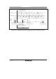
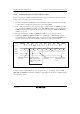
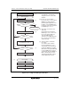
Figure 15.20 Sample Flowchart of Simultaneous Serial Transmit and Receive Operations