
Datasheet

Section 15 Serial Communication Interface (SCI, IrDA)
Page 920 of 1384 R01UH0310EJ0500 Rev. 5.00
Sep 25, 2012
H8S/2426, H8S/2426R, H8S/2424 Group
15.6.3 Serial Data Transmission (Clocked Synchronous Mode)
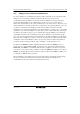
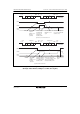
Figure 15.16 shows an example of SCI operation for transmission in clocked synchronous mode.
In serial transmission, the SCI operates as described below.
1. The SCI monitors the TDRE flag in SSR, and if is 0, recognizes that data has been written to
TDR, and transfers the data from TDR to TSR.
2. After transferring data from TDR to TSR, the SCI sets the TDRE flag to 1 and starts
transmission. If the TIE bit in SCR is set to 1 at this time, a TXI interrupt request is generated.
Because the TXI interrupt routine writes the next transmit data to TDR before transmission of
the current transmit data has finished, continuous transmission can be enabled.
3. 8-bit data is sent from the TxD pin synchronized with the output clock when output clock
mode has been specified and synchronized with the input clock when use of an external clock
has been specified.
4. The SCI checks the TDRE flag at the timing for sending the MSB.
5. If the TDRE flag is cleared to 0, data is transferred from TDR to TSR, and serial transmission
of the next frame is started.
6. If the TDRE flag is set to 1, the TEND flag in SSR is set to 1, and the TxD pin maintains the
output state of the last bit. If the TEIE bit in SCR is set to 1 at this time, a TEI interrupt request
is generated. The SCK pin is fixed high.
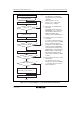
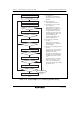
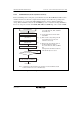
Figure 15.17 shows a sample flowchart for serial data transmission. Even if the TDRE flag is
cleared to 0, transmission will not start while a receive error flag (ORER, FER, or PER) is set to 1.
Make sure to clear the receive error flags to 0 before starting transmission. Note that clearing the
RE bit to 0 does not clear the receive error flags.