
Datasheet

Section 15 Serial Communication Interface (SCI, IrDA)
R01UH0310EJ0500 Rev. 5.00 Page 909 of 1384
Sep 25, 2012
H8S/2426, H8S/2426R, H8S/2424 Group
Yes
<End>
[1]
No
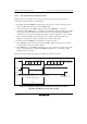
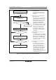
Initialization
Start of reception
[2]
No
Yes
Read RDRF flag in SSR
[4]
[5]
Clear RE bit in SCR to 0
Read ORER, PER, and
FER flags in SSR
Error handling
(Continued on next page)
[3]
Read receive data in RDR, and
clear RDRF flag in SSR to 0
No
Yes
PER ∨ FER ∨ ORER = 1?
RDRF = 1?
All data received?
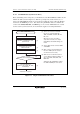
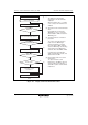
SCI initialization:
The RxD pin is automatically
designated as the receive data
input pin.
Receive error handling and
break detection:
If a receive error occurs, read the
ORER, PER, and FER flags in
SSR to identify the error. After
performing the appropriate error
processing, ensure that the
ORER, PER, and FER flags are
all cleared to 0. Reception cannot
be resumed if any of these flags
are set to 1. In the case of a
framing error, a break can be
detected by reading the value of
the input port corresponding to
the RxD pin.
SCI status check and receive
data read :
Read SSR and check that RDRF
= 1, then read the receive data in
RDR and clear the RDRF flag to
0. Transition of the RDRF flag
from 0 to 1 can also be identified
by an RXI interrupt.
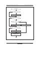
Serial reception continuation
procedure:
To continue serial reception,
before the stop bit for the current
frame is received, read the
RDRF flag, read RDR, and clear
the RDRF flag to 0. The RDRF
flag is cleared automatically
when the DMAC or DTC is
activated by an RXI interrupt and
the RDR value is read.
[1]
[2] [3]
[4]
[5]
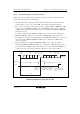
Figure 15.9 Sample Serial Reception Data Flowchart (1)