
Datasheet

Section 15 Serial Communication Interface (SCI, IrDA)
Page 902 of 1384 R01UH0310EJ0500 Rev. 5.00
Sep 25, 2012
H8S/2426, H8S/2426R, H8S/2424 Group
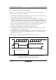
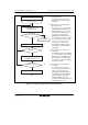
15.4.2 Receive Data Sampling Timing and Reception Margin in Asynchronous Mode
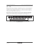
In asynchronous mode, the SCI operates on a basic clock with a frequency of 16 times the bit rate.
In reception, the SCI samples the falling edge of the start bit using the basic clock, and performs
internal synchronization. Receive data is latched at the middle of each bit by sampling the data at
the rising edge of the 8th pulse of the basic clock as shown in figure 15.3. Thus the reception
margin in asynchronous mode is given by formula (1) below.
M = { (0.5 – ) – (L – 0.5) F – (1 + F) } × 100 [%]
1
2N
⏐
D – 0.5
⏐
N
... Formula (1)
Where M: Reception Margin
N: Ratio of bit rate to clock (N = 16)
D: Clock duty cycle (D = 0.5 to 1.0)
L: Frame length (L = 9 to 12)
F: Absolute value of clock rate deviation
Assuming values of F = 0 and D = 0.5 in formula (1), a reception margin is given by formula
below.
M = {0.5 – 1/(2 × 16)} × 100 [%] = 46.875%
However, this is only the computed value, and a margin of 20% to 30% should be allowed in
system design.
Internal base
clock
16 clocks
8 clocks
Receive data
(RxD)
Synchronization
sampling timing
Start bit D0 D1
Data sampling
timing
15 0 7 15 00
7
Figure 15.3 Receive Data Sampling Timing in Asynchronous Mode