
Datasheet

Section 15 Serial Communication Interface (SCI, IrDA)
R01UH0310EJ0500 Rev. 5.00 Page 897 of 1384
Sep 25, 2012
H8S/2426, H8S/2426R, H8S/2424 Group
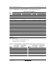
15.3.10 IrDA Control Register (IrCR)
IrCR selects the function of SCI_0.
Bit Bit Name Initial Value R/W Description
7 IrE 0 R/W IrDA Enable
Specifies normal SCI mode or IrDA mode for
SCI_0 input/output.
0: Pins TxD0/IrTxD and RxD0/IrRxD function as
TxD0 and RxD0
1: Pins TxD0/IrTxD and RxD0/IrRxD function as
IrTxD and IrRxD
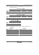
6
5
4
IrCKS2
IrCKS1
IrCKS0
0
0
0
R/W
R/W
R/W
IrDA Clock Select 2 to 0
Specifies the high pulse width in IrTxD output
pulse encoding when the IrDA function is enabled.
000: Pulse width = B × 3/16 (3/16 of bit rate)
001: Pulse width = φ/2
010: Pulse width = φ/4
011: Pulse width = φ/8
100: Pulse width = φ/16
101: Pulse width = φ/32
110: Pulse width = φ/64
111: Pulse width = φ/128
3 IrTxINV 0 R/W IrTx Data Invert
Specifies the logic level of the IrTxD output to be
inverted. When inversion is performed, the high
pulse width specified by bits 6 to 4 becomes the
low pulse width.
0: Transmit data is used as IrTxD output without
change
1: Transmit data is inverted before used as IrTxD
output