
Datasheet


Section 15 Serial Communication Interface (SCI, IrDA)
Page 890 of 1384 R01UH0310EJ0500 Rev. 5.00
Sep 25, 2012
H8S/2426, H8S/2426R, H8S/2424 Group
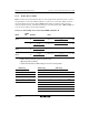
Table 15.3 shows sample N settings in BRR in normal asynchronous mode. Table 15.4 shows the
maximum bit rate for each frequency in normal asynchronous mode. Table 15.6 shows sample N
settings in BRR in clocked synchronous mode. Table 15.8 shows sample N settings in BRR in
Smart Card interface mode. In Smart Card interface mode, S (the number of basic clock cycles in
a 1-bit transfer interval) can be selected. For details, refer to section 15.7.4, Receive Data
Sampling Timing and Reception Margin. Tables 15.5 and 15.7 show the maximum bit rates with
external clock input.
The bit rate should be twice the value in table 15.3 when the ABCS bit in the serial expansion
mode register of the SCI_2 (SEMR_2) is 1 in asynchronous mode.
Table 15.3 BRR Settings for Various Bit Rates (Asynchronous Mode)
Operating Frequency φ (MHz)
8 9.8304 10 12
Bit Rate
(bit/s)
n N
Error
(%) n N
Error
(%) n N
Error
(%) n N
Error
(%)
110 2 141 0.03 2 174 –0.26 2 177 –0.25 2 212 0.03
150 2 103 0.16 2 127 0.00 2 129 0.16 2 155 0.16
300 1 207 0.16 1 255 0.00 2 64 0.16 2 77 0.16
600 1 103 0.16 1 127 0.00 1 129 0.16 1 155 0.16
1200 0 207 0.16 0 255 0.00 1 64 0.16 1 77 0.16
2400 0 103 0.16 0 127 0.00 0 129 0.16 0 155 0.16
4800 0 51 0.16 0 63 0.00 0 64 0.16 0 77 0.16
9600 0 25 0.16 0 31 0.00 0 32 –1.36 0 38 0.16
19200 0 12 0.16 0 15 0.00 0 15 1.73 0 19 –2.34
31250 0 7 0.00 0 9 –1.70 0 9 0.00 0 11 0.00
38400 ⎯ ⎯ ⎯ 0 7 0.00 0 7 1.73 0 9 –2.34