
Datasheet


Section 15 Serial Communication Interface (SCI, IrDA)
R01UH0310EJ0500 Rev. 5.00 Page 889 of 1384
Sep 25, 2012
H8S/2426, H8S/2426R, H8S/2424 Group
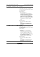
15.3.9 Bit Rate Register (BRR)
BRR is an 8-bit register that adjusts the bit rate. As the SCI performs baud rate generator control
independently for each channel, different bit rates can be set for each channel. Table 15.2 shows
the relationships between the N setting in BRR and bit rate B for normal asynchronous mode,
clocked synchronous mode, and Smart Card interface mode. The initial value of BRR is H'FF, and
it can be read or written to by the CPU at all times.
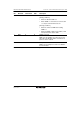
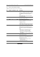
Table 15.2 Relationships between N Setting in BRR and Bit Rate B
Mode
ABCS
Bit Bit Rate Error
0
N =− 1
64 × 2
2n−1
× B
φ × 10
6
Error (%) = {
B × 64 × 2
2n−1
× (N + 1)
− 1 } × 100
φ × 10
6
Asynchronous
Mode
1
− 1N =
32 × 2
2n−1
× B
φ × 10
6
Error (%) = {
B × 32 × 2
2n−1
× (N + 1)
− 1 } × 100
φ × 10
6
Clocked Synchronous
Mode
− 1N =
8 × 2
2n−1
× B
φ × 10
6
Smart Card Interface
Mode
− 1N =
S × 2
2n+1
× B
φ × 10
6
Error (%) = {
B × S × 2
2n+1
× (N + 1)
− 1 } × 100
φ × 10
6
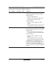
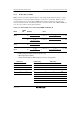
Note: B: Bit rate (bit/s)
N: BRR setting for baud rate generator (0 ≤ N ≤ 255)
φ: Operating frequency (MHz)
n and S: Determined by the SMR settings shown in the following tables.
SMR Setting SCMR Setting SMR Setting
CKS1 CKS0 n BCP2 BCP1 BCP0 S
0 0 0 0 0 0 93
0 1 1 0 0 1 128
1 0 2 0 1 0 186
1 1 3 0 1 1 512
1 0 0 32
1 0 1 64
1 1 0 372
1 1 1 256