
Datasheet


Section 14 Watchdog Timer (WDT)
Page 858 of 1384 R01UH0310EJ0500 Rev. 5.00
Sep 25, 2012
H8S/2426, H8S/2426R, H8S/2424 Group
14.4 Operation
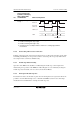
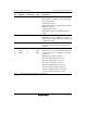
14.4.1 Watchdog Timer Mode
To use the WDT as a watchdog timer mode, set the WT/IT and TME bits in TCSR to 1.
If TCNT overflows without being rewritten because of a system crash or other error, the
WDTOVF signal is output.
This ensures that TCNT does not overflow while the system is operating normally. Software must
prevent TCNT overflows by rewriting the TCNT value (normally be writing H'00) before
overflow occurs. This WDTOVF signal can be used to reset the chip internally in watchdog timer
mode.
If TCNT overflows when 1 is set in the RSTE bit in RSTCSR, a signal that resets this LSI
internally is generated at the same time as the WDTOVF signal. If a reset caused by a signal input
to the RES pin occurs at the same time as a reset caused by a WDT overflow, the RES pin reset
has priority and the WOVF bit in RSTCSR is cleared to 0.
The WDTOVF signal is output for 132 states when RSTE = 1, and for 130 states when RSTE = 0.
The internal reset signal is output for 518 states.
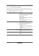
When TCNT overflows in watchdog timer mode, the WOVF bit in RSTCSR is set to 1. If TCNT
overflows when 1 is set in the RSTE bit in RSTCSR, an internal reset signal is generated to the
entire chip.