
Datasheet


Section 13 8-Bit Timers (TMR)
R01UH0310EJ0500 Rev. 5.00 Page 851 of 1384
Sep 25, 2012
H8S/2426, H8S/2426R, H8S/2424 Group
No.
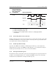
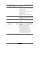
Timing of Switchover
by Means of Modifying
CKS1, CKS0, ICKS1,
and ICKS0 Bits TCNT Clock Operation
4 Switching from high
to high
Clock before
switchover
Clock after
switchover
TCNT clock
TCNT
CKS bit write
N
N + 1 N + 2
Notes: 1. Includes switching from low to stop, and from stop to low.
2. Includes switching from stop to high.
3. Includes switching from high to stop.
4. Generated on the assumption that the switchover is a falling edge; TCNT is
incremented.
13.8.6 Mode Setting with Cascaded Connection
If 16-bit counter mode and compare match count mode are specified at the same time, input clocks
for TCNT_0 and TCNT_1 are not generated, and the counter stops. Do not specify 16-bit counter
and compare match count modes simultaneously.
13.8.7 Module Stop Function Setting
Operation of the TMR can be disabled or enabled using the module stop control register. The
initial setting is for operation of the TMR to be halted. Register access is enabled by clearing the
module stop state. For details, refer to section 23, Power-Down Modes.
13.8.8 Interrupts in Module Stop State
If a transition is made to the module stop state when an interrupt has been requested, it will not be
possible to clear the CPU interrupt source or the DTC and DMAC activation source. Interrupts
should therefore be disabled before entering the module stop state.