
Datasheet


Section 13 8-Bit Timers (TMR)
Page 844 of 1384 R01UH0310EJ0500 Rev. 5.00
Sep 25, 2012
H8S/2426, H8S/2426R, H8S/2424 Group
13.6 Operation with Cascaded Connection
If bits CKS2 to CKS0 in either TCR_0 or TCR_1 are set to B'100, the 8-bit timers of the two
channels are cascaded. With this configuration, a single 16-bit timer could be used (16-bit counter
mode) or compare matches of the 8-bit channel 0 could be counted by the timer of channel 1
(compare match count mode). In this case, the timer operates as below.
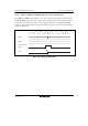
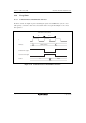
13.6.1 16-Bit Counter Mode
When bits CKS2 to CKS0 in TCR_0 are set to B'100, the timer functions as a single 16-bit timer
with channel 0 occupying the upper 8 bits and channel 1 occupying the lower 8 bits.
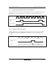
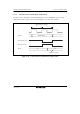
[1] Setting of compare match flags
• The CMF flag in TCSR_0 is set to 1 when a 16-bit compare match event occurs.
• The CMF flag in TCSR_1 is set to 1 when a lower 8-bit compare match event occurs.
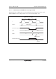
[2] Counter clear specification
• If the CCLR1 and CCLR0 bits in TCR_0 have been set for counter clear at compare match, the
16-bit counters (TCNT_0 and TCNT_1 together) are cleared when a 16-bit compare match
event occurs. The 16-bit counters (TCNT0 and TCNT1 together) are cleared even if counter
clear by the TMRI0 pin has also been set.
• The settings of the CCLR1 and CCLR0 bits in TCR_1 are ignored. The lower 8 bits cannot be
cleared independently.
[3] Pin output
• Control of output from the TMO0 pin by bits OS3 to OS0 in TCSR_0 is in accordance with the
16-bit compare match conditions.
• Control of output from the TMO1 pin by bits OS3 to OS0 in TCSR_1 is in accordance with the
lower 8-bit compare match conditions.
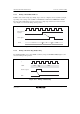
13.6.2 Compare Match Count Mode
When bits CKS2 to CKS0 in TCR_1 are B'100, TCNT_1 counts compare match A's for channel 0.
Channels 0 and 1 are controlled independently. Conditions such as setting of the CMF flag,
generation of interrupts, output from the TMO pin, and counter clear are in accordance with the
settings for each channel.