
Datasheet

Section 13 8-Bit Timers (TMR)
Page 840 of 1384 R01UH0310EJ0500 Rev. 5.00
Sep 25, 2012
H8S/2426, H8S/2426R, H8S/2424 Group
13.5 Operation Timing
13.5.1 TCNT Incrementation Timing
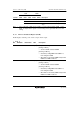
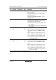
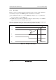
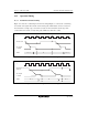
Figure 13.4 shows the count timing for internal clock input. Figure 13.5 shows the count timing
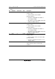
for external clock signal. Note that the external clock pulse width must be at least 1.5 states for
incrementation at a single edge, and at least 2.5 states for incrementation at both edges. The
counter will not increment correctly if the pulse width is less than these values.
Internal clock
φ
Clock input
to TCNT
TCNT N – 1 N N + 1
Figure 13.4 Count Timing for Internal Clock Input
External clock
input pin
φ
Clock input
to TCNT
TCNT N – 1 N N + 1
Figure 13.5 Count Timing for External Clock Input