
Datasheet

Section 13 8-Bit Timers (TMR)
Page 838 of 1384 R01UH0310EJ0500 Rev. 5.00
Sep 25, 2012
H8S/2426, H8S/2426R, H8S/2424 Group
13.4 Operation
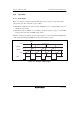
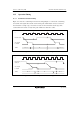
13.4.1 Pulse Output
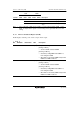
Figure 13.2 shows an example in which the 8-bit timer is used to generate a pulse output with a
selected duty cycle. The control bits are set as follows:
[1] In TCR, the CCLR1 bit is cleared to 0 and the CCLR0 bit is set to 1 so that TCNT is cleared at
a TCORA compare match.
[2] In TCSR, the OS3 to OS0 bits are set to B'0110, causing the output to change to 1 at a TCORA
compare match and to 0 at a TCORB compare match.
With these settings, the 8-bit timer provides output of pulses at a rate determined by TCORA with
a pulse width determined by TCORB. No software intervention is required.
TCNT
H'FF
Counter clear
TCORA
TCORB
H'00
TMO
Figure 13.2 Example of Pulse Output