
Datasheet

Section 13 8-Bit Timers (TMR)
Page 834 of 1384 R01UH0310EJ0500 Rev. 5.00
Sep 25, 2012
H8S/2426, H8S/2426R, H8S/2424 Group
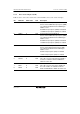
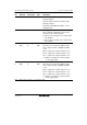
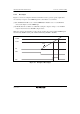
TCR TCCR
Channel
Bit 2
CKS2
Bit 1
CKS1
Bit 0
CKS0
Bit 1
ICKS1
Bit 0
ICKS0 Description
All 1 0 1 ⎯ ⎯ External clock, counted at rising edge
1 0 ⎯ ⎯ External clock, counted at falling edge
1 1 ⎯ ⎯ External clock, counted at both rising and falling
edges
Note: * If the count input of TMR_0 is the TCNT_1 overflow signal and that of TMR_1 is the
TCNT_0 compare match signal, no incrementing clock is generated. Do not use this
setting.
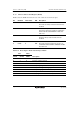
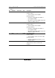
13.3.6 Timer Control/Status Register (TCSR)
TCSR displays status flags, and controls compare match output.
• TCSR_0
Bit Bit Name Initial Value R/W Description
7 CMFB 0 R/(W)
*
Compare Match Flag B
[Setting condition]
• Set when TCNT matches TCORB
[Clearing conditions]
• Cleared by reading CMFB when CMFB = 1,
then writing 0 to CMFB
• When DTC is activated by CMIB interrupt while
DISEL bit of MRB in DTC is 0
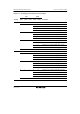
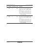
6 CMFA 0 R/(W)
*
Compare Match Flag A
[Setting condition]
• Set when TCNT matches TCORA
[Clearing conditions]
• Cleared by reading CMFA when CMFA = 1,
then writing 0 to CMFA
• When DTC is activated by CMIA interrupt while
DISEL bit of MRB in DTC is 0