
Datasheet
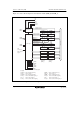

Section 13 8-Bit Timers (TMR)
R01UH0310EJ0500 Rev. 5.00 Page 829 of 1384
Sep 25, 2012
H8S/2426, H8S/2426R, H8S/2424 Group
13.2 Input/Output Pins
Table 13.1 shows the pin configuration of the 8-bit timer module.
Table 13.1 Pin Configuration
Channel Name Symbol I/O Function
0 Timer output pin TMO0 Output Outputs at compare match
Timer clock input pin TMCI0 Input Inputs external clock for counter
Timer reset input pin TMRI0 Input Inputs external reset to counter
1 Timer output pin TMO1 Output Outputs at compare match
Timer clock input pin TMCI1 Input Inputs external clock for counter
Timer reset input pin TMRI1 Input Inputs external reset to counter
13.3 Register Descriptions
The 8-bit timer module has the following registers. For details on the module stop control register,
refer to section 23.1.2, Module Stop Control Registers H and L (MSTPCRH, MSTPCRL).
• Timer counter_0 (TCNT_0)
• Time constant register A_0 (TCORA_0)
• Time constant register B_0 (TCORB_0)
• Timer control register_0 (TCR_0)
• Timer control/status register_0 (TCSR_0)
• Timer counter control register_0 (TCCR_0)
• Timer counter_1 (TCNT_1)
• Time constant register A_1 (TCORA_1)
• Time constant register B_1 (TCORB_1)
• Timer control register_1 (TCR_1)
• Timer control/status register_1 (TCSR_1)
• Timer counter control register_1 (TCCR_1)