
Datasheet

Section 11 16-Bit Timer Pulse Unit (TPU)
R01UH0310EJ0500 Rev. 5.00 Page 777 of 1384
Sep 25, 2012
H8S/2426, H8S/2426R, H8S/2424 Group
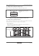
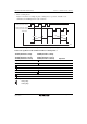
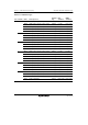
(3) Phase Counting Mode Application Example
Figure 11.30 shows an example in which phase counting mode is designated for channel 1, and
channel 1 is coupled with channel 0 to input servo motor 2-phase encoder pulses in order to detect
the position or speed.
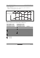
Channel 1 is set to phase counting mode 1, and the encoder pulse A-phase and B-phase are input
to TCLKA and TCLKB.
Channel 0 operates with TCNT counter clearing by TGRC_0 compare match; TGRA_0 and
TGRC_0 are used for the compare match function, and are set with the speed control cycle and
position control cycle. TGRB_0 is used for input capture, with TGRB_0 and TGRD_0 operating
in buffer mode. The channel 1 counter input clock is designated as the TGRB_0 input capture
source, and detection of the pulse width of 2-phase encoder 4-multiplication pulses is performed.
TGRA_1 and TGRB_1 for channel 1 are designated for input capture, channel 0 TGRA_0 and
TGRC_0 compare matches are selected as the input capture source, and the up/down-counter
values for the control cycles are stored.
This procedure enables accurate position/speed detection to be achieved.