
Datasheet

Section 11 16-Bit Timer Pulse Unit (TPU)
R01UH0310EJ0500 Rev. 5.00 Page 771 of 1384
Sep 25, 2012
H8S/2426, H8S/2426R, H8S/2424 Group
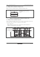
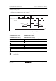
11.4.6 Phase Counting Mode
In phase counting mode, the phase difference between two external clock inputs is detected and
TCNT is incremented/decremented accordingly. This mode can be set for channels 1, 2, 4, 5, 7, 8,
10, and 11.
When phase counting mode is set, an external clock is selected as the counter input clock and
TCNT operates as an up/down-counter regardless of the setting of bits TPSC2 to TPSC0 and bits
CKEG1 and CKEG0 in TCR. However, the functions of bits CCLR1 and CCLR0 in TCR, and of
TIOR, TIER, and TGR are valid, and input capture/compare match and interrupt functions can be
used.
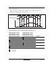
This can be used for two-phase encoder pulse input.
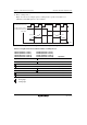
When overflow occurs while TCNT is counting up, the TCFV flag in TSR is set; when underflow
occurs while TCNT is counting down, the TCFU flag is set.
The TCFD bit in TSR is the count direction flag. Reading the TCFD flag provides an indication of
whether TCNT is counting up or down.
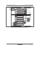
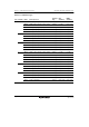
Table 11.32 shows the correspondence between external clock pins and channels.
Table 11.32 Clock Input Pins in Phase Counting Mode
External Clock Pins
Unit Channels A-Phase B-Phase
0 When channel 1 or 5 is set to phase counting mode TCLKA TCLKB
When channel 2 or 4 is set to phase counting mode TCLKC TCLKD
1 When channel 7 or 11 is set to phase counting mode TCLKE TCLKF
When channel 8 or 10 is set to phase counting mode TCLKG TCLKH