
Datasheet

Section 11 16-Bit Timer Pulse Unit (TPU)
R01UH0310EJ0500 Rev. 5.00 Page 767 of 1384
Sep 25, 2012
H8S/2426, H8S/2426R, H8S/2424 Group
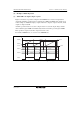
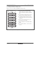
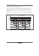
(1) Example of PWM Mode Setting Procedure
Figure 11.21 shows an example of the PWM mode setting procedure.
Select counter clock
PWM mode
Select counter clearing source
Select waveform output level
<PWM mode>
[1]
[2]
[3]
Set TGR [4]
Set PWM mode [5]
Start count [6]
[1] Select the counter clock with bits TPSC2 to
TPSC0 in TCR. At the same time, select the
input clock edge with bits CKEG1 and CKEG0 in
TCR.
[2] Use bits CCLR2 to CCLR0 in TCR to select the
TGR to be used as the TCNT clearing source.
[3] Use TIOR to designate the TGR as an output
compare register, and select the initial value and
output value.
[4] Set the cycle in the TGR selected in [2], and
set the duty in the other TGRs.
[5] Select the PWM mode with bits MD3 to MD0 in
TMDR.
[6] Set the CST bit in TSTR to 1 to start the count
operation.
Figure 11.21 Example of PWM Mode Setting Procedure