
Datasheet

Section 11 16-Bit Timer Pulse Unit (TPU)
Page 764 of 1384 R01UH0310EJ0500 Rev. 5.00
Sep 25, 2012
H8S/2426, H8S/2426R, H8S/2424 Group
(2) Examples of Cascaded Operation
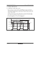
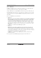
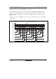
Figure 11.19 illustrates the operation when counting upon TCNT_2 overflow/underflow has been
set for TCNT_1, TGRA_1 and TGRA_2 have been designated as input capture registers, and the
TIOC pin rising edge has been selected.
When a rising edge is input to the TIOCA1 and TIOCA2 pins simultaneously, the upper 16 bits of
the 32-bit data are transferred to TGRA_1, and the lower 16 bits to TGRA_2.
TCNT_2
clock
TCNT_2 H'FFFF H'0000
H'0001
TIOCA1,
TIOCA2
TGRA_1
H'03A2
TGRA_2
H'0000
TCNT_1
clock
TCNT_1 H'03A1 H'03A2
Figure 11.19 Example of Cascaded Operation (1)
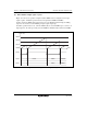
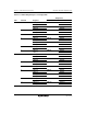
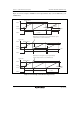
Figure 11.20 illustrates the operation when counting upon TCNT_2 overflow/underflow has been
set for TCNT_1, and phase counting mode has been designated for channel 2.
TCNT_1 is incremented by TCNT_2 overflow and decremented by TCNT_2 underflow.
TCLKC
TCNT_2
FFFD
TCNT_1
0001
TCLKD
FFFE
FFFF 0000 0001 0002 0001 0000 FFFF
0000 0000
Figure 11.20 Example of Cascaded Operation (2)