
Datasheet

Section 11 16-Bit Timer Pulse Unit (TPU)
R01UH0310EJ0500 Rev. 5.00 Page 763 of 1384
Sep 25, 2012
H8S/2426, H8S/2426R, H8S/2424 Group
11.4.4 Cascaded Operation
In cascaded operation, two 16-bit counters for different channels are used together as a 32-bit
counter.
This function works by counting the channel 1 (channel 4, channel 7, or channel 10) counter clock
at overflow/underflow of TCNT_2 (TCNT_5, TCNT_8, or TCNT_11) as set in bits TPSC2 to
TPSC0 in TCR.
Underflow occurs only when the lower 16-bit TCNT is in phase-counting mode.
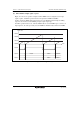
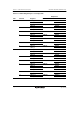
Table 11.30 shows the register combinations used in cascaded operation.
Note: When phase counting mode is set for channel 1, 4, 7, or 10, the counter clock setting is
invalid and the counter operates independently in phase counting mode.
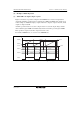
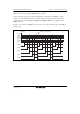
Table 11.30 Cascaded Combinations
Combination Upper 16 Bits Lower 16 Bits
Channels 1 and 2 TCNT_1 TCNT_2
Channels 4 and 5 TCNT_4 TCNT_5
Channels 7 and 8 TCNT_7 TCNT_8
Channels 10 and 11 TCNT_10 TCNT_11
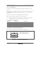
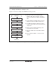
(1) Example of Cascaded Operation Setting Procedure
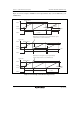
Figure 11.18 shows an example of the setting procedure for cascaded operation.
Cascaded operation
Set cascading
Start count
<Cascaded operation>
Set bits TPSC2 to TPSC0 in the channel 1
(channel 4) TCR to B'1111 to select TCNT_2
(TCNT_5) overflow/underflow counting.
Set the CST bit in TSTR for the upper and lower
channel to 1 to start the count operation.
[1]
[2]
[1]
[2]
Figure 11.18 Cascaded Operation Setting Procedure