
Datasheet

Section 11 16-Bit Timer Pulse Unit (TPU)
Page 758 of 1384 R01UH0310EJ0500 Rev. 5.00
Sep 25, 2012
H8S/2426, H8S/2426R, H8S/2424 Group
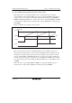
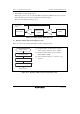
(2) Example of Synchronous Operation
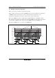
Figure 11.12 shows an example of synchronous operation.
In this example, synchronous operation and PWM mode 1 have been designated for channels 0 to
2, TGRB_0 compare match has been set as the channel 0 counter clearing source, and
synchronous clearing has been set for the channel 1 and 2 counter clearing source.
Three-phase PWM waveforms are output from pins TIOCA0, TIOCA1, and TIOCA2. At this
time, synchronous presetting, and synchronous clearing by TGRB_0 compare match, is performed
for channel 0 to 2 TCNT counters, and the data set in TGRB_0 is used as the PWM cycle.
For details on PWM modes, see section 11.4.5, PWM Modes.
TCNT0 to TCNT2 values
H'0000
TIOCA_0
TIOCA_1
TGRB_0
Synchronous clearing by TGRB_0 compare match
TGRA_2
TGRA_1
TGRB_2
TGRA_0
TGRB_1
TIOCA_2
Time
Figure 11.12 Example of Synchronous Operation