
Datasheet

Section 11 16-Bit Timer Pulse Unit (TPU)
R01UH0310EJ0500 Rev. 5.00 Page 755 of 1384
Sep 25, 2012
H8S/2426, H8S/2426R, H8S/2424 Group
(3) Input Capture Function
The TCNT value can be transferred to TGR on detection of the TIOC pin input edge.
Rising edge, falling edge, or both edges can be selected as the detection edge. For channels 0, 1, 3,
4, 6, 7, 9, and 10 it is also possible to specify another channel's counter input clock or compare
match signal as the input capture source.
Note: When another channel's counter input clock is used as the input capture input for channels
0, 3, 6, and 9, φ/1 should not be selected as the counter input clock used for input capture
input. Input capture will not be generated if φ/1 is selected.
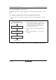
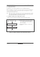
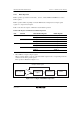
(a) Example of setting procedure for input capture operation
Figure 11.9 shows an example of the setting procedure for input capture operation.
Select input capture input
Input selection
Start count
<Input capture operation>
[1]
[2]
[1] Designate TGR as an input capture register by
means of TIOR, and select the input capture
source and input signal edge (rising edge, falling
edge, or both edges).
[2] Set the CST bit in TSTR to 1 to start the count
operation.
Figure 11.9 Example of Setting Procedure for Input Capture Operation