
Datasheet


Section 11 16-Bit Timer Pulse Unit (TPU)
R01UH0310EJ0500 Rev. 5.00 Page 723 of 1384
Sep 25, 2012
H8S/2426, H8S/2426R, H8S/2424 Group
11.3.3 Timer I/O Control Register (TIOR)
TIOR registers control the TGR registers. The TPU has eight TIOR registers, two each for
channels 0 and 3, and one each for channels 1, 2, 4, and 5. Care is required since TIOR is affected
by the TMDR setting.
The initial output specified by TIOR is valid when the counter is stopped (the CST bit in TSTR is
cleared to 0). Note also that, in PWM mode 2, the output at the point at which the counter is
cleared to 0 is specified.
When TGRC or TGRD is designated for buffer operation, this setting is invalid and the register
operates as a buffer register.
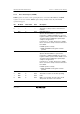
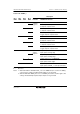
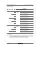
TIORH_0, TIOR_1, TIOR_2, TIORH_3, TIOR_4, TIOR_5
Bit Bit Name Initial Value R/W Description
7
6
5
4
IOB3
IOB2
IOB1
IOB0
0
0
0
0
R/W
R/W
R/W
R/W
I/O Control B3 to B0
Specify the function of TGRB.
For details, see tables 11.13, 11.15, 11.16, 11.17,
11.19, and 11.20.
3
2
1
0
IOA3
IOA2
IOA1
IOA0
0
0
0
0
R/W
R/W
R/W
R/W
I/O Control A3 to A0
Specify the function of TGRA.
For details, see tables 11.21, 11.23, 11.24, 11.25,
11.27, and 11.28.
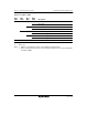
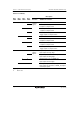
TIORL_0, TIORL_3
Bit Bit Name Initial Value R/W Description
7
6
5
4
IOD3
IOD2
IOD1
IOD0
0
0
0
0
R/W
R/W
R/W
R/W
I/O Control D3 to D0
Specify the function of TGRD.
For details, see tables 11.14 and 11.18.
3
2
1
0
IOC3
IOC2
IOC1
IOC0
0
0
0
0
R/W
R/W
R/W
R/W
I/O Control C3 to C0
Specify the function of TGRC.
For details, see tables 11.22 and 11.26.