
Datasheet


Section 11 16-Bit Timer Pulse Unit (TPU)
R01UH0310EJ0500 Rev. 5.00 Page 721 of 1384
Sep 25, 2012
H8S/2426, H8S/2426R, H8S/2424 Group
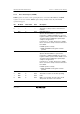
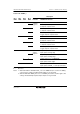
11.3.2 Timer Mode Register (TMDR)
TMDR registers are used to set the operating mode for each channel. The TPU has six TMDR
registers, one for each channel. TMDR register settings should be made only when TCNT
operation is stopped.
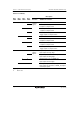
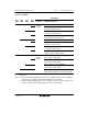
Bit Bit Name Initial Value R/W Description
7
6
⎯
⎯
1
1
⎯
⎯
Reserved
These bits are always read as 1 and cannot be
modified.
5 BFB 0 R/W Buffer Operation B
Specifies whether TGRB is to operate in the
normal way, or TGRB and TGRD are to be used
together for buffer operation. When TGRD is used
as a buffer register, TGRD input capture/output
compare is not generated.
In channels 1, 2, 4, and 5, which have no TGRD,
bit 5 is reserved. It is always read as 0 and cannot
be modified.
0: TGRB operates normally
1: TGRB and TGRD used together for buffer
operation
4 BFA 0 R/W Buffer Operation A
Specifies whether TGRA is to operate in the
normal way, or TGRA and TGRC are to be used
together for buffer operation. When TGRC is used
as a buffer register, TGRC input capture/output
compare is not generated.
In channels 1, 2, 4, and 5, which have no TGRC,
bit 4 is reserved. It is always read as 0 and cannot
be modified.
0: TGRA operates normally
1: TGRA and TGRC used together for buffer
operation
3
2
1
0
MD3
MD2
MD1
MD0
0
0
0
0
R/W
R/W
R/W
R/W
Modes 3 to 0
These bits are used to set the timer operating
mode.
MD3 is a reserved bit. The write value should
always be 0. See table 11.12 for details.