
Datasheet


Section 11 16-Bit Timer Pulse Unit (TPU)
Page 716 of 1384 R01UH0310EJ0500 Rev. 5.00
Sep 25, 2012
H8S/2426, H8S/2426R, H8S/2424 Group
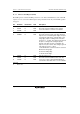
11.3.1 Timer Control Register (TCR)
The TCR registers control the TCNT operation for each channel. The TPU has a total of six TCR
registers, one for each channel. TCR register settings should be made only when TCNT operation
is stopped.
Bit Bit Name Initial Value R/W Description
7
6
5
CCLR2
CCLR1
CCLR0
0
0
0
R/W
R/W
R/W
Counter Clear 2 to 0
These bits select the TCNT counter clearing
source. See tables 11.4 and 11.5 for details.
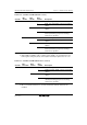
4
3
CKEG1
CKEG0
0
0
R/W
R/W
Clock Edge 1 and 0
These bits select the input clock edge. When the
input clock is counted using both edges, the input
clock period is halved (e.g. φ/4 both edges = φ/2
rising edge). If phase counting mode is used on
channels 1, 2, 4, and 5, this setting is ignored and
the phase counting mode setting has priority.
Internal clock edge selection is valid when the
input clock is φ/4 or slower. This setting is ignored
if the input clock is φ/1, or when
overflow/underflow of another channel is selected.
00: Count at rising edge
01: Count at falling edge
1x: Count at both edges
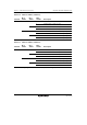
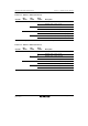
2
1
0
TPSC2
TPSC1
TPSC0
0
0
0
R/W
R/W
R/W
Time Prescaler 2 to 0
These bits select the TCNT counter clock. The
clock source can be selected independently for
each channel. See tables 11.6 to 11.11 for details.
[Legend]
x: Don't care